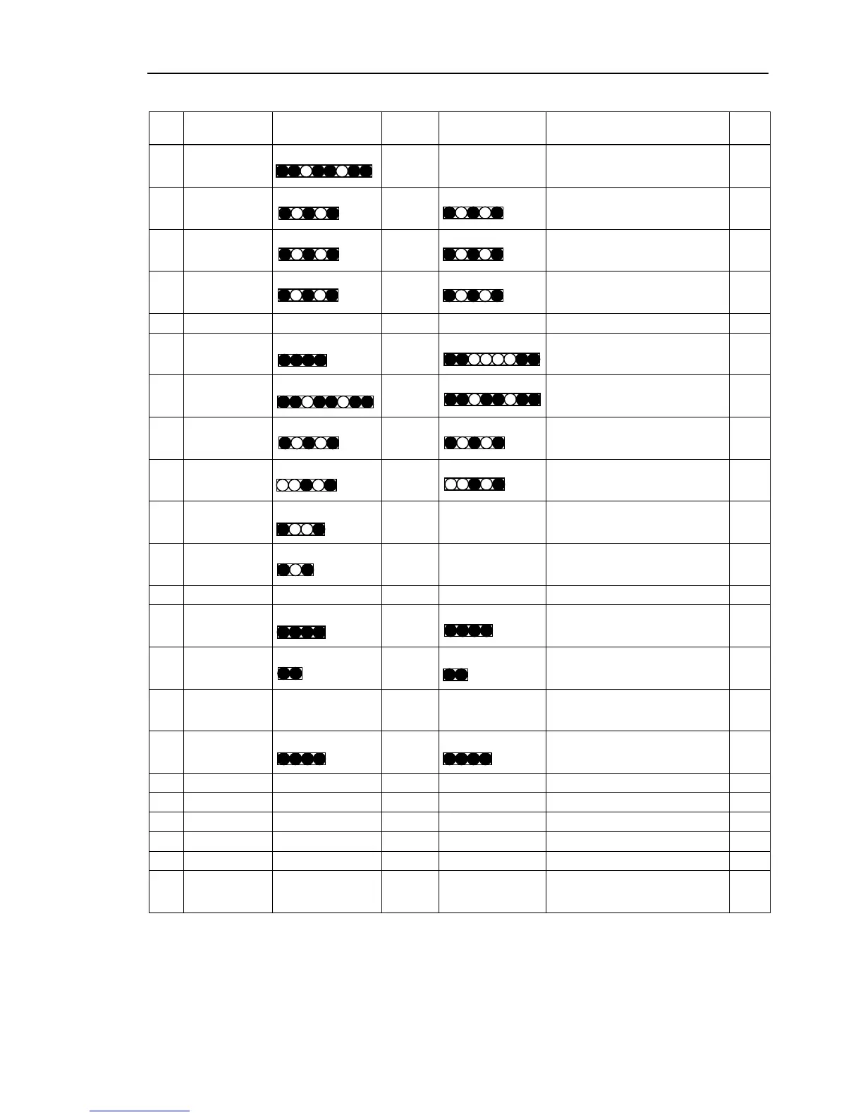
EasyManuals Logo

Epson RC180 User Manual

Epson RC180
264 pages
To Next Page IconTo Next Page
To Previous Page IconTo Previous Page
Page #135 background imageLoading...
Page #135 background image
Maintenance 3. Controller Structure
RC180 Rev.17 123
RC180
Cable List
Cable
No.
Connection
Connector Pin
Quantity
Wire
Quantity
Connector Pin
Quantity
Connection Note
(1) DPB
8
6 Noise Filter
(2) DPB
5
3
5
Switching Power Supply (5V)
(3) DPB
5
3
5
Switching Power Supply (24V)
(4) DPB
5
3
5
Switching Power Supply (15V)
(5) DPB 26 26<F> 25(D-SUB) EMERGENCY
(6) DPB
4
4
8
Switching Power Supply (24V)
(7) DPB
8
6
8
DMB
(8) DPB
5
3
5
ProSix Driver Unit I/F Board
*1
(9) DPB
5
2
5
Regeneration Board
(10)
Regeneration
Board
4
2 Regeneration Resistance
(11)
Regeneration
Board
3
2 Resistance
(12) DMB 34 34<F> 34 Encoder I/F Board
(13) DMB
4
4
4
Switching Power Supply (15V)
(14) DMB
2
2
2
ProSix Driver Unit I/F Board
*1
(15) CPU Board
50
34<F>
16<F>
34
16
DPB
Encoder I/F Board
(16) CPU Board
4
4
4
Switching Power Supply (5V)
(17) CPU Board 3 3
Fan
(18)
CPU Board
3
3
Fan
(19) CPU Board 2 2
Temperature Sensor
(20) CPU Board 80 80<F> 80 Back Plane Board
*3
(21)
M/C POWER
50
16
4,4,4,4
DMB
(22) M/C POWER
50
16
14
4,4,4,4
4,4,8
DMB
ProSix Driver Unit I/F Board
*1
<F> Flat cable
*1 When connected to ProSix Driver unit
*3 When connected to Option unit

Table of Contents

Other manuals for Epson RC180

Questions and Answers:

Question and Answer IconNeed help?

Do you have a question about the Epson RC180 and is the answer not in the manual?

Epson RC180 Specifications

General IconGeneral
BrandEpson
ModelRC180
CategoryController
LanguageEnglish

Related product manuals