Maintenance 6. Maintenance Parts Replacement Procedures
RC180 Rev.17 151
Connected to the G10 or G20 series manipulator
Start from Mount step (1).
Connected to the G1, G3, G6,
RS, C3 or S5 series manipulator
Start from Mount step (3).
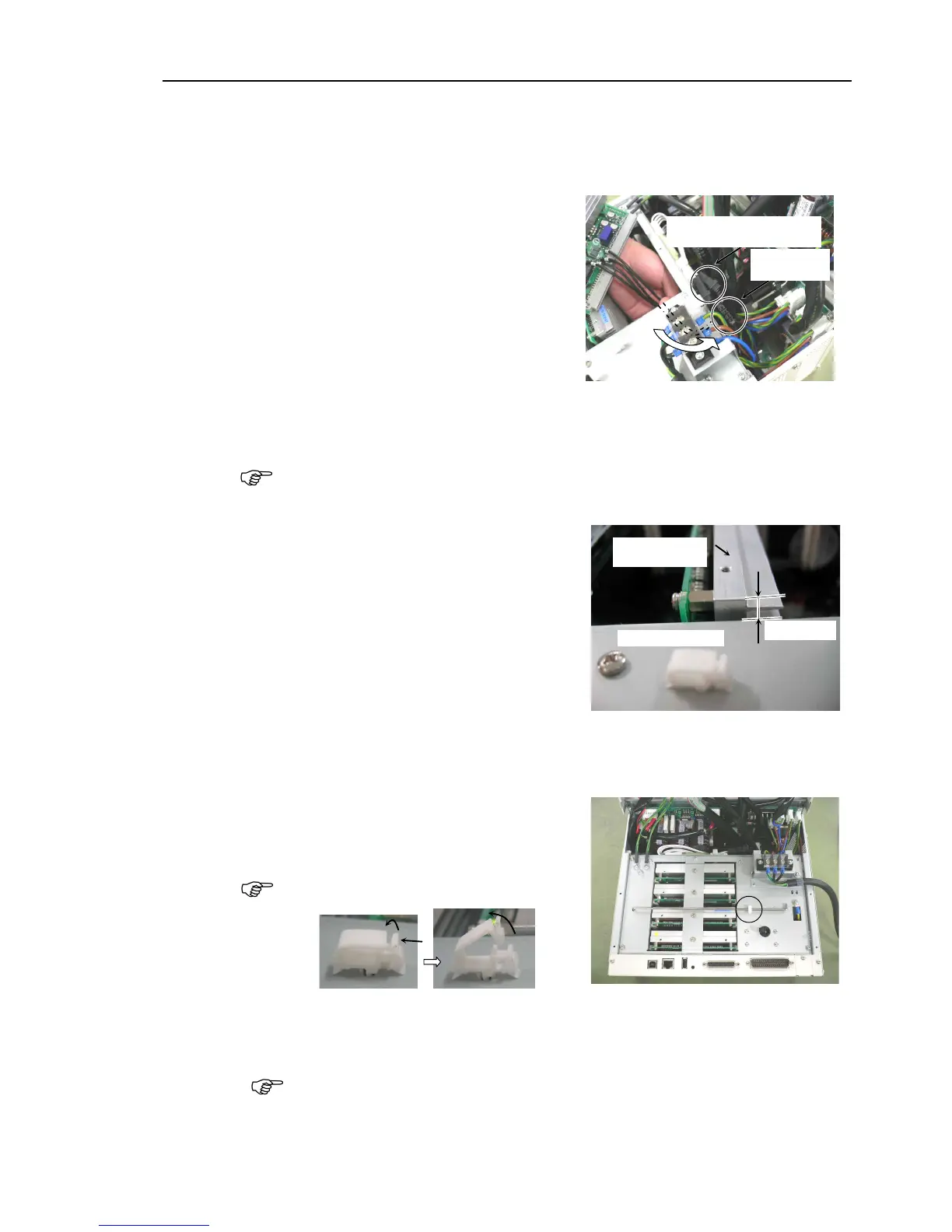
When replacing the first or the second
motor driver, insert the connector
connected to the motor driver carefully
along the guide rail through the rear
side of the intermediate plate
Cement
Resistance Connector
Connect the connector connected to the replacing first or second motor driver to the
cement resistance connector.
There are two cement resistance connectors.
he connector for the motor driver can
be connected to either one of them.
Connect to the resistance connector in the
the Motor Driver along the guide
the surface height differences
the Motor Driver comes to 5 mm or
Top Surface of
Motor Driver
two Motor Driver connectors.
the Motor Driver mounting bracket with five screws.
the front cover and put the front cover support bar back to the normal position.
the front cover support bar with the
Push latch A as shown in the photo first
and open up the clamp.
the two screws on the side of the front cover.
the front cover and secure it with four screws.
Make sure to keep cables from becoming trapped or damaged.