Epson Stylus NX510/515/SX510W/515W/TX550W/NX415/SX410/415/TX410/419/NX215/SX210/215/TX210/213/219/ME OFFICE 510 Revision A
DISASSEMBLY/ASSEMBLY Disassembling the Printer Mechanism 121
Confidential
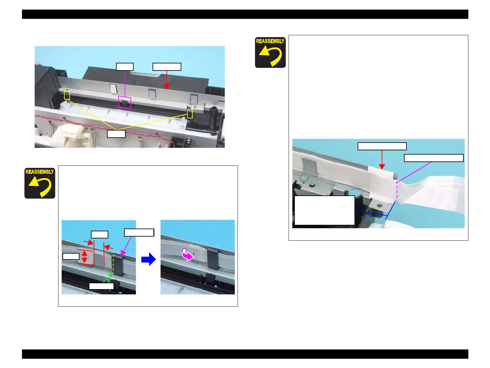
7. Release the hook (x1), and remove the Front Frame.
Figure 4-56. Removing the Front Frame/Right Frame (4)
NX510 series only:
Align the ferrite core with the line mark shown in Figure
4-57, then secure it to the Front Frame with double-sided
tape.
After replacing the Front Frame, be sure to attach acetate
tape as shown in the figure below.
Figure 4-57. Standard of acetate tape attachment
When installing the Front Frame, pay attention to the
following instructions.
• As shown in Figure 4-56, be sure to secure the Front Frame
with the hook (x1) and the cutouts (x2).
• As shown in Figure 4-55, secure the Front Frame and Right
Frame together with the screw. (Place the Right Frame on
top of the Front Frame.)
Before securing the Porous Pad Frame Right, align the hole
of the Porous Pad Frame Right with the dowel of the Right
Frame as shown in
Figure 4-54.
SX410/SX210 series only:
Secure the Head FFCs (x3) to the Front Frame with the
acetate tape (x1) as shown in the figure below.
Figure 4-58. Acetate Tape Position
Acetate Tape (35mm)
Bending Point of Head FFC
Align the edge of the Front
Frame with the bending
point of the Head FFC, and
secure the FFC with the
acetate tape.
 Loading...