Epson Stylus NX510/515/SX510W/515W/TX550W/NX415/SX410/415/TX410/419/NX215/SX210/215/TX210/213/219/ME OFFICE 510 Revision A
DISASSEMBLY/ASSEMBLY Disassembling the Printer Mechanism 133
Confidential
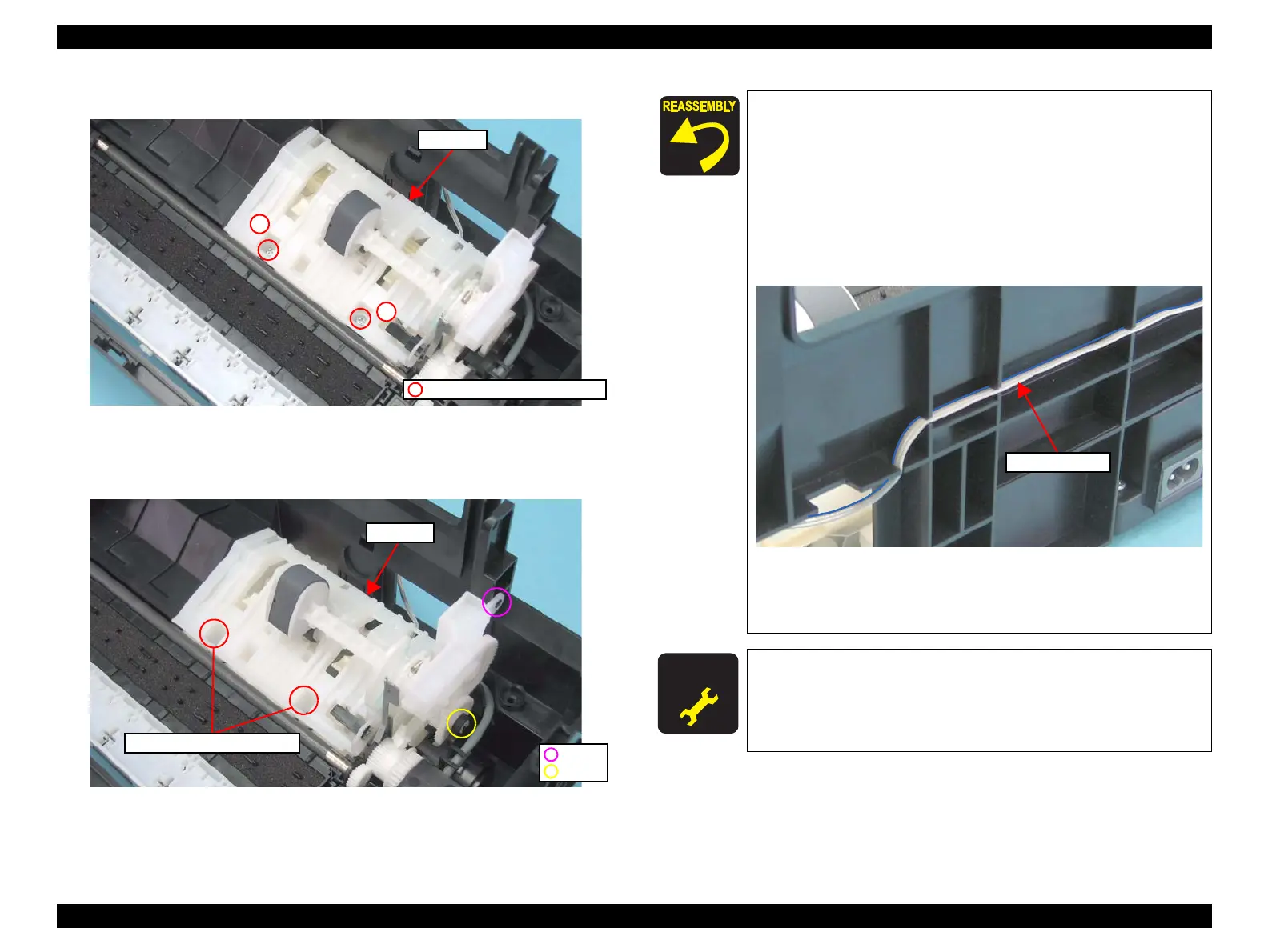
2. Remove the screws (x2) that secure the ASF Unit.
Figure 4-89. Removing the ASF Unit (1)
3. Release the dowel (x1) and guide pins (x2) of the Base Frame and the shaft
(x1) of the ASF Unit, then remove the ASF Unit.
Figure 4-90. Removing the ASF Unit (2)
C.B.P. 3x8, F/Zn-3C (6±1kgfcm)
1
2
ASF Unit
ASF Unit
Dowel
Shaft
Guide Pin and Positioning Hole
When installing the ASF Unit, be sure to align the guide pins
(x2) of the Base Frame with the positioning holes (x2) of the
ASF Unit as shown in
Figure 4-90.
Tighten the screws in the order given in Figure 4-89.
When routing the PE Sensor cable, pay attention to the
following instructions.
• Route the cable in the order given in Figure 4-87.
• Make sure to attach the cable with the blue line facing
toward the Base Frame.
Figure 4-91. Routing PE Sensor Cable
• Check that the cable is tightly routed and there is no slack of
it.
A D J U S T M E N T
R E Q U I R E D
Whenever the ASF Unit is removed/replaced, the required
adjustments must be carried out.
• Chapter 5 “ ADJUSTMENT” (p.161)
 Loading...