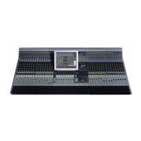
Euphonix Max Air Mixing Console Operations Manual Quickstart to Common Tasks
37
Meters3.5
After channels are assigned to the surface, set the meters to suit your needs.
Setting the Fader Meters On Each Strip3.5.1
We recommend beginning here since you will be able to see signal when you patch into
the channel.
Select 1. Meters from the Main Menu.
Select the 2. Fader tab.
This view shows all available Strips on your Max Air Console.
Touch 3. Select All, then choose Fader in the Meter Display area to the right to en-
able the meter next to each fader on the Strips.
When you begin patching audio into console, you will now see signal on each
channel as you patch.
Screen Meters on the Touchscreen3.5.2
There are eight meter banks across the top and down the right side of the Touchscreen.
You can choose from a wide variety of signals to display here. Since there are meters set
up on every channel, it is probably best to select the screen meter area to display Sub-
groups, Aux Masters, Solo, and Program. In this example we will place the meters for
these busses on the screen.
Select 1. Meters from the Main Menu.
Select the 2. Screen tab.
Select the left-most meter bank area (selected bank shows a yellow outline box).3.
To select the four stereo subgroup masters we created earlier, press the 4. Main Sec-
tions button in the Function area.
Select Main section 5. A (labeled SubA in the Main Section box).
You will see the SubA stereo meters appear in the selected bank.
Select the adjacent meter bank to the right and repeat above steps until SubA, 6.
SubB, SubC, and SubD meters are visible.
On the fth meter bank from the left, place eight Aux masters:
Select the fth meter bank area from the left.7.
Select 8. Aux Busses from the Function area – the available aux busses buttons ap-
pear on the right area of the screen.

 Loading...