6 Positioning mode
142 Festo – GDCP-CMMS/D-FW-EN – 1404NH – English
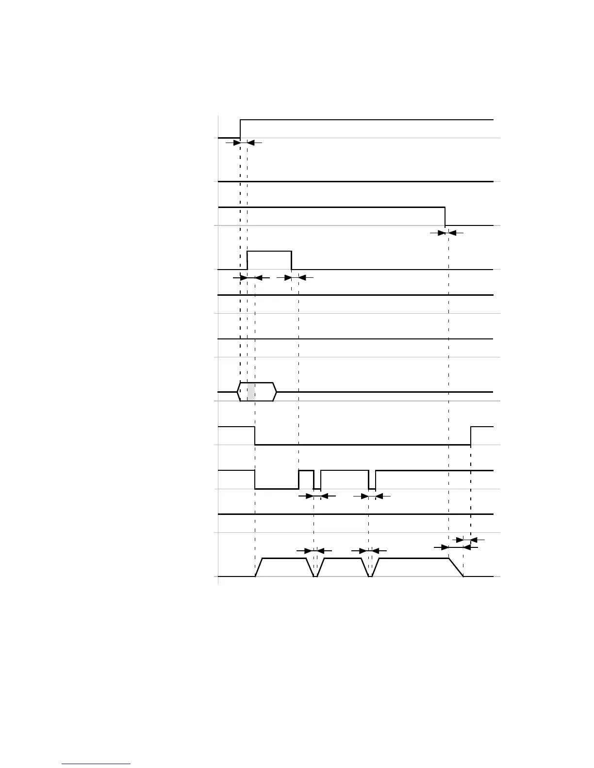
Timing diagra m: Cancelling the record sequence via mode bit 1
The timing diagram shows the cancellation of the record sequence via mode bit 1 (DIN9).
Star t record sequence
(DIN8)[X1.23]
Stop
(DIN13)[X1.15]
Halt record sequence
(DIN3)[X1.8]
Motion complete
(DOUT1)[X1.12]
Mode bit 1
(DIN9)[X1.11]
Confirm start
(DOUT2)[X1.25]
Common error
(DOUT3)[X1.13]
Speed
(Positioning record 1/2/3)
t2
1
Record selection bit 0…2
(Positioning record 1…7)
(DIN…)[X1.…]
t3
t1
t2
t3
23
t5
Controller read
for o
eration
(DOUT0)[X1.24]
Mode bit 0
(DIN12)[X1.2]
t7
t6
t4 t4
t1 ≥ 2.5 ms
t2 ≤ 5ms
t3 L 16 ms
t4 ≤ 2.5 ms
t5 ≤ 2.5 ms
t6 = … ms (dependent on reaching the position
of the current positioning record)
t7 = … ms (FCT: Dependent on the parameters
“Message window” and “D amping time” in
the message “Destination re ached”)
Fig. 6.17 Timing diagram: Cancelling the record sequence via mode bit 1
 Loading...


