3 Control interfaces
Festo – GDCP-CMMS/D-FW-EN – 1404NH – Engli sh 63
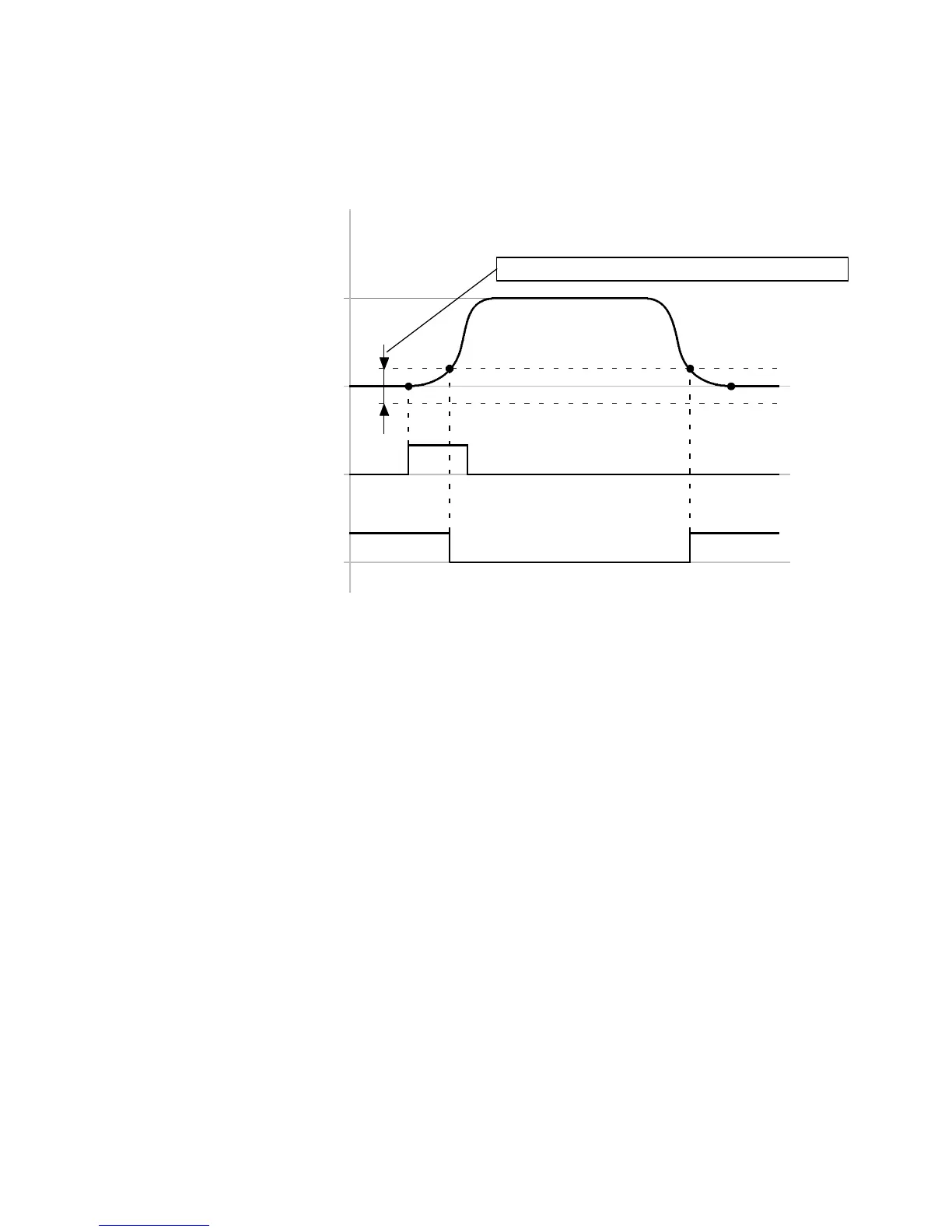
Timing diagram: Digital output signal “Standstill reached”
The timing diagram shows the dependency of the digital output signal “Standstill reached” on the mes-
sage window “Speed reached”.
Standstill reached
(DOUT1/2/3)[X1.12/25/13]
Standstill
+
–
Δv
Message window “Speed reached”
Start
(DIN8)[X1.23]
Parameter
“speed”
Δv = + /– … mm/s (linear axis) or
= +/– … rpm ( rotative axis)
(FCT: Dependent on the parameter “Message window” in the message “Speed reached”)
Fig. 3.9 Timing diagram: Digital output signal “Standstill reached”
 Loading...


