2. I/O data and sequence control
2−7
Festo P.BE−CPX−CMA X−CONTROL−EN en 0908NH
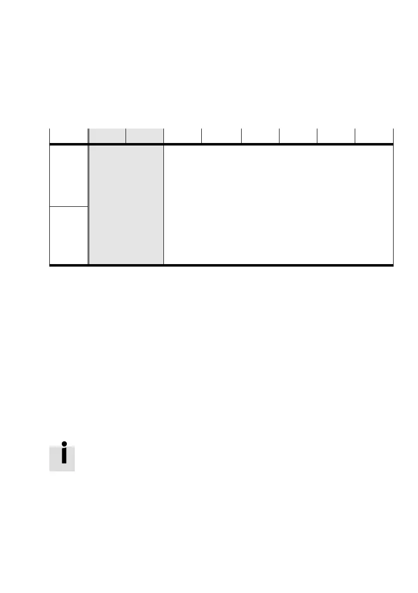
2.2 Structure of the cyclical I/O data in the operating modes
Data Byte 1 Byte 2 Byte 3 Byte 4 Byte 5 Byte 6 Byte 7 Byte 8
Output
data
Bytes 1 and 2 (fixed)
are retained in every
operating mode
(except byte 2 for
parametrisation).
The
contain control
Bytes 3 to 8 depend on the selected operating mode (direct mode,
record select) and transmit further control and status bytes (e.g.
CDIR, SDIR,...), as well as setpoint and actual values:
Record number or setpoint position in the output data
Feedback of actual position and record number in the input data
Additional o
eratin
mode− and control mode−de
endent set
Input
data
and status bytes
(e.g. CCON,
SCON, ...) for enab
ling the CMAX and
setting the operat
ing modes
point and actual values
Procedure
First define the operating mode in the CCON control byte. See
sections 2.2.1 and 2.2.2.
This results in the assignment of the other control and status
bytes:
Record select mode, see section 2.2.3.
Direct operating mode, see section 2.2.4.
Commissioning mode, see section 2.2.5
Parametrising mode, see section 2.2.6.
Recommendation: During operation, set the control
bit
CCON.LOCK. This way, the PLC can ensure that the pro
grammed sequence cannot be disturbed by access with
the FCT.
Evaluate the status bit SCON.FCT_MMI, and take the missing
control access into consideration in the program sequence of
the PLC.

 Loading...