B. Basic controlling principles
B−13
Festo P.BE−CPX−CMA X−CONTROL−EN en 0908NH
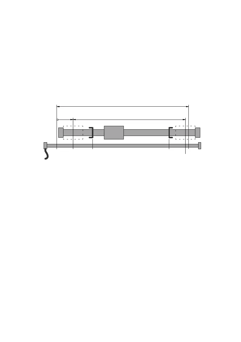
B.2.4 Software end positions / Hardware end positions
The software end positions may only be set within certain
limits depending on the projected hardware. The parameters
as shown in Fig.B/3 will be taken into account.
CZ/AZ USELSESZ
1
23
45 6 78
1
Measuring system length:
PNU 1111
2 Cylinder length: PNU 1101
3 Offset to the axis zero point:
PNU 1130
4 Measuring system zero point
5 Lower hardware end position
= minimum permissible lower software end
position
6 Lower software end position: PNU 501:01
7 Upper software end position: PNU 501:02
8 Upper hardware end position
= maximum permissible upper software end
position
Fig.B/3: Parameters for software end positions
These limits result from the length of the measuring system
and the cylinder as well as the mounting offset between the
two. The mounting offset is given based on the offset of the
measuring system zero point to
the axis zero point.
The two limit values are referred to as hardware end posi
tions". If the user sets both software end positions to 0, in
order to deactivate them, all setpoint specifications are li
mited to the hardware end positions.
If position control is active, the set tolerance is taken into
account, so that minor overswings when starting up the soft
ware end positions do not lead to an error.

 Loading...