B. Basic controlling principles
B−9
Festo P.BE−CPX−CMA X−CONTROL−EN en 0908NH
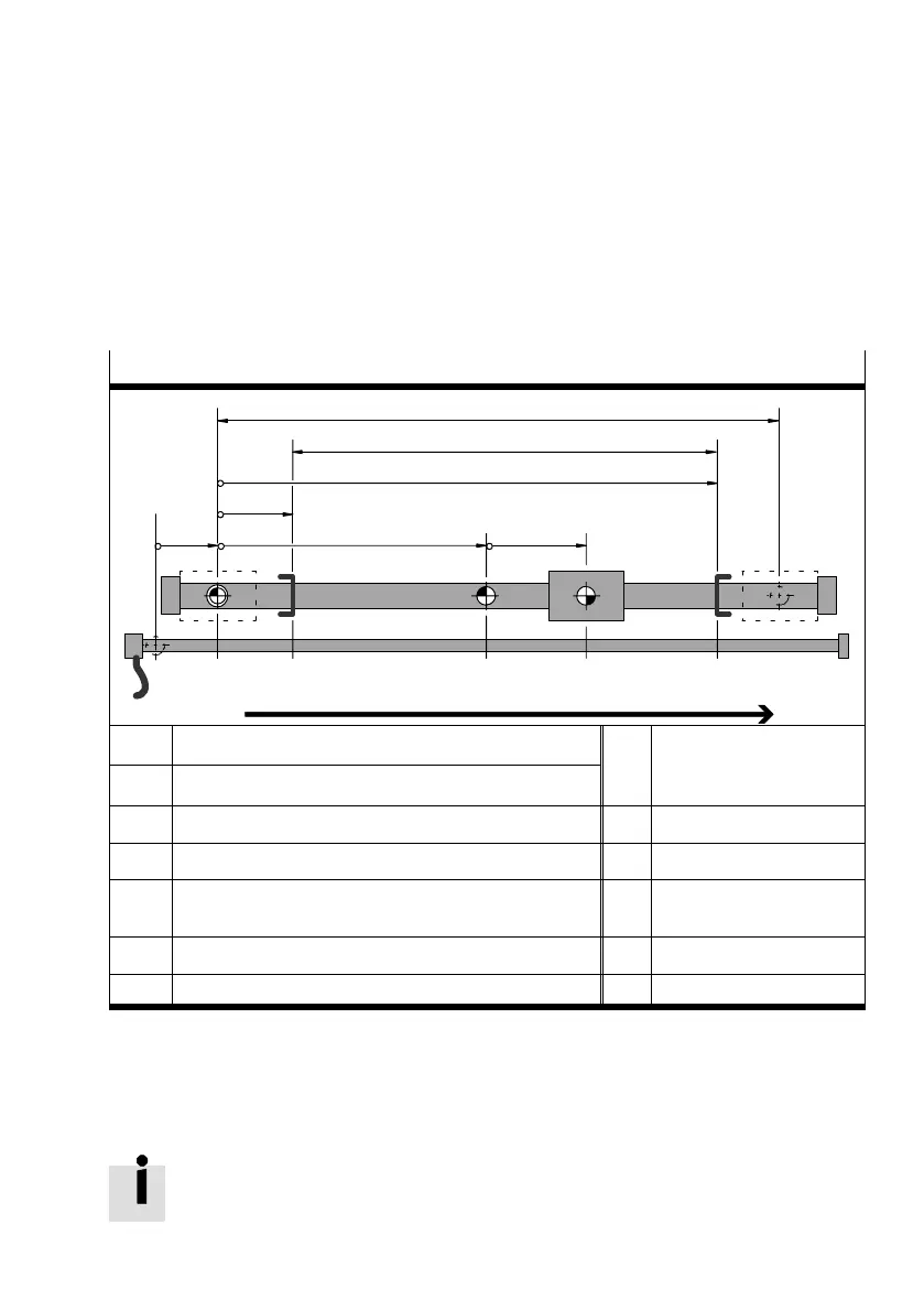
B.2 Dimension reference system for pneumatic drives
B.2.1 Dimension reference system with absolute measuring system
System of units for linear drives with absolute measuring system
1
CZ/AZ
a’ b c
PZ
d
e
TP/AP USELSE
Positions increasing in size, positive" travel, right−hand" travel
SZ
SZ Sensor/measu rin g system zero poin t (sensor zero point)
a’ Offset axis zero poin t
CZ C ylinder zero point, stop
stance
−
, so
ar
mounting offset")
AZ Axis zero point b Offset project zero point
PZ Project zero point c Offset target/actual position
LSE Lower software end position d, e Offset software end posi
tion s :
USE Upper software end position 1 Effective stroke
TP, AP Target/ actua l position 2 Cy linder/axis length
Tab.B/7: Dimension reference system for pneumatic drives with absolute measuring system
The vectors a’ to e are user specifications provided these
cannot be recognised (e.g. cylinder and measuring system
length with the DGCI).
The axis zero point always has to be on the cylinder zero
point! This is necessary because the controller requires the
absolute
piston position within the cylinder.

 Loading...