B. Basic controlling principles
B−40
Festo P.BE−CPX−CMA X−CONTROL−EN en 0908NH
The maximum force applied to the piston is referred to as
nominal force F
N
, and it is calculated as follows:
F
N
[N] = A
N
* p
operation
The maximum forces applied to the drive for both direc
tions of movement are calculated as follows: With non−
horizontal mounting position (
α š 0 for linear drives, refer
to Fig.B/2) they are dependent on direction and mass:
F
max+
[N] = + 0.9 * A
N
* p
operation
m
current
* g * sin α
F
max
[N] = 0.9 * (A
N
A
KS
) * p
operation
m
current
* g *
sin
α
This contains the following user data:
p
operation
= supply pressure
A
N
= nominal piston surface
(e.g. DNCI−25−...: A
N
= / 4 * 0.025
2
)
A
KS
= piston rod surface
m
current
= m
current
tool
mass
+ m
current
workpi ece
mass
α = mounting position
The values for F
max+
and F
max
are calculated in the con
troller. The controller limits the user data to these limit
values and reports a fault if necessary.
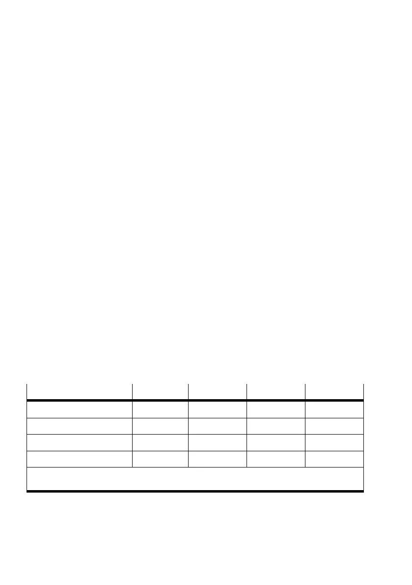
Parameter
Unit FCT default Minimum Maximum
Force tolerance N 10 1 1.000
Force ramp N/s 1.000 10 10.000
Speed limit value mm/s 200 10
1)
500
Stroke limit value mm 50 1
1)
10.000
1)
The speed and stroke limit values can be deactivated for every force record, so entering 0 is not
permissible.

 Loading...