7 Connection
7.1 FLUXUS *601 FLUXUS F60*
2017-10-16, UMFLUXUSF60xV5-0EN
52
7.1.3 Outputs
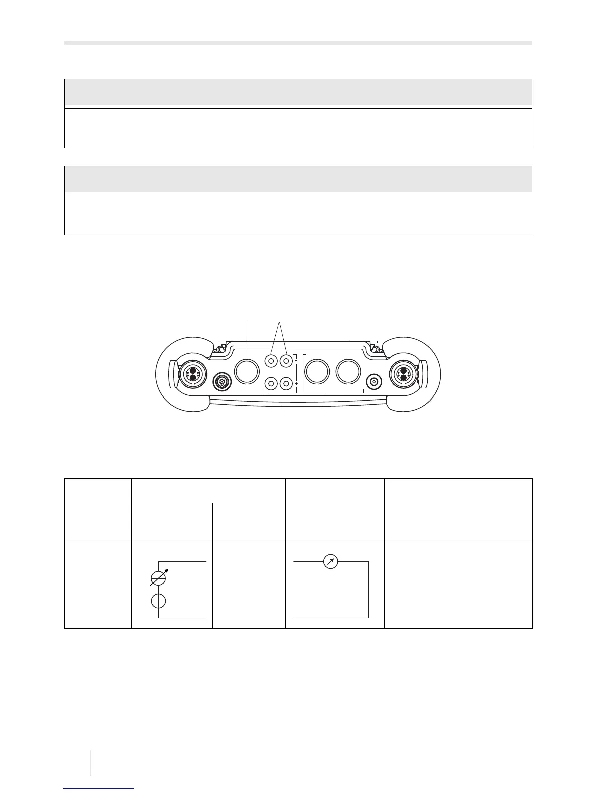
For the connection of the outputs, see Fig. 7.4 and Tab. 7.1.
For the connection, observe the specifications regarding the assignment of the out-
puts given on the nameplate on the backside of the transmitter.
The max. voltage between the outputs and the internal power supply of the transmit-
ter is 42 V DC (permanent).
Fig. 7.4: Connection of the transmitter outputs
1 – outputs
2 – output adapter
Tab. 7.1: Circuit of the outputs
output transmitter external circuit remark
internal
circuit
connection
active
current
output
R
ext
< 750 Ω
(U
int
= 24 V DC)
The number, type and the connections of the outputs depend on the order.
R
ext
is the sum of all ohmic resistances in the circuit (e.g., resistance of the conductors, resistance of
the amperemeter/voltmeter).
 Loading...


