ix
List of Figures
Figure Title Page
1-1. 2640A/2645A NetDAQ Networked Data Acquisition Units.......................... 1-3
1-2. 2640A/2645A Front Panel .............................................................................. 1-4
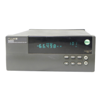
1-3. Typical Front Panel Display During Scanning and Monitoring ..................... 1-5
1-4. 2640A/2645A Rear Panel................................................................................ 1-6
2-1. Instrument Preparation.................................................................................... 2-4
2-2. Connecting the Instrument to a Power Source................................................ 2-6
2-3. Universal Input Module Connections ............................................................. 2-9
2-4. 2-Wire and 4-Wire Connections..................................................................... 2-10
2-5. DIGITAL I/O Connector................................................................................. 2-12
2-6. ALARM/TRIGGER I/O Connector ................................................................ 2-14
2-7. External Trigger Wiring for a Group Instrument............................................ 2-16
2-8. Front Panel Controls........................................................................................ 2-17
2-9. Front Panel Indicators ..................................................................................... 2-18
2-10. Rear Panel Controls......................................................................................... 2-20
2-11. Rear Panel Indicators ...................................................................................... 2-20
2-12. Displaying a Monitor Channel........................................................................ 2-22
2-13. Examples During Monitor............................................................................... 2-23
2-14. Displaying the Digital I/O Status .................................................................... 2-24
2-15. Examples for Digital I/O and Totalizer Status................................................ 2-25
2-16. Displaying the Totalizer Status....................................................................... 2-26
2-17. Reviewing and Setting the Base Channel Number ......................................... 2-27
2-18. Examples for Reviewing and Setting the BCN............................................... 2-28
2-19. Reviewing and Setting the Line Frequency .................................................... 2-29
2-20. Examples for Reviewing and Setting the Line Frequency.............................. 2-30
2-21. Reviewing and Setting the Isolated Network Type to Isolated....................... 2-31
2-22. Examples for Reviewing and Setting the Network Type................................ 2-32
2-23. Reviewing and Setting the Network Type to General..................................... 2-33
2-24. Examples for Reviewing and Setting General Network Parameters............... 2-34
2-25. Reviewing and Setting the General Network Socket Port .............................. 2-36
2-26. Reviewing and Setting the General Network IP Address ............................... 2-37
2-27. Reviewing and Setting the Subnet Mask and Default Gateway...................... 2-40