2640A/2645A NetDAQ
Users Manual
2-14
+
9-16V
DC PWR
MA TO TI
ALARM/TRIGGER I/O
TR3210–+
+
–
MA
TO
TI
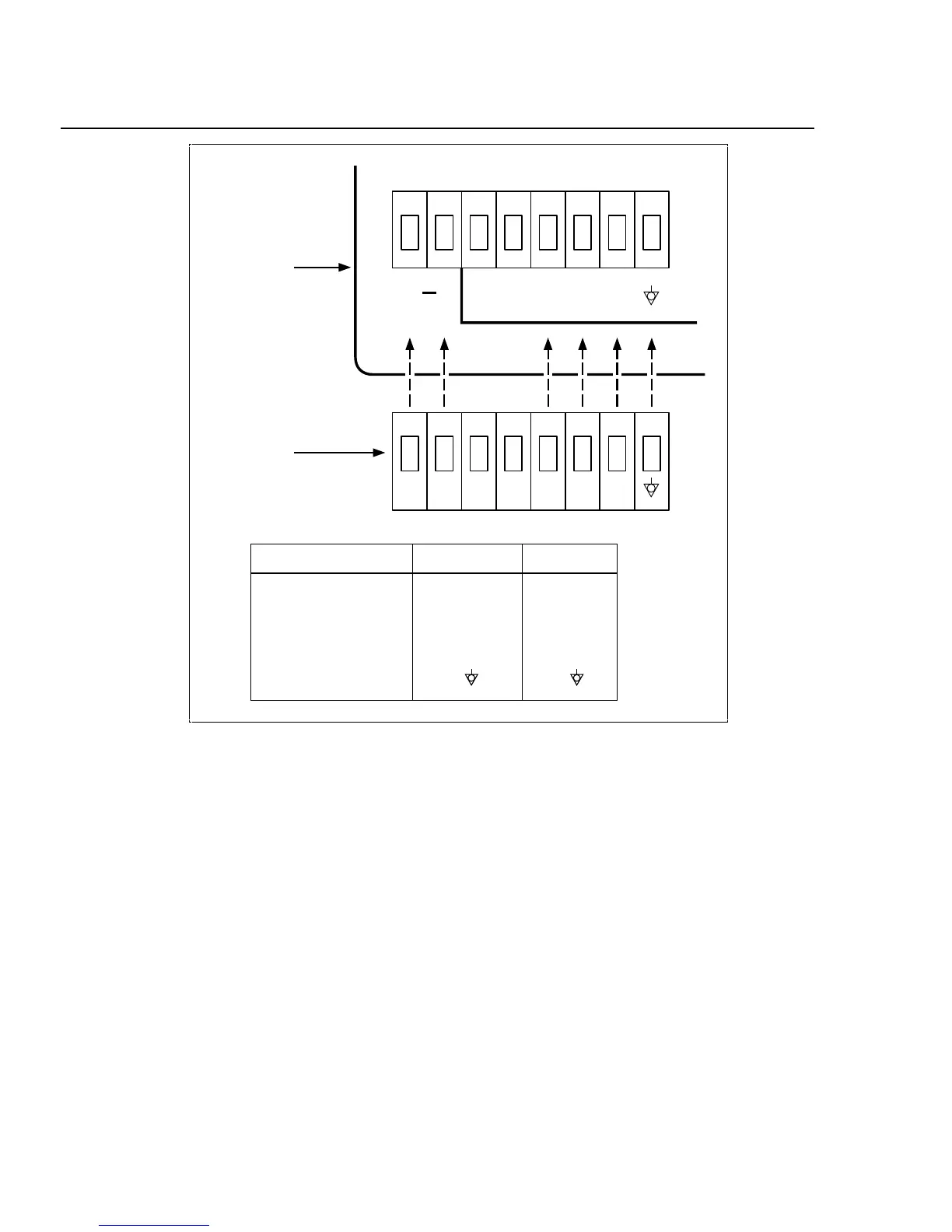
DC Positive Input
DC Negative Input
Master Alarm Output
Trigger Out Output
Trigger In Input
Signal Ground
Instrument
Connector
+
–
2
3
TR
InstrumentFunction Connector
Figure 2-6. ALARM/TRIGGER I/O Connector
Trigger Output 2-17.
Trigger Output uses terminals TO and GND, and is a TTL signal that goes to a
logic low for 125 µs every time a scan begins. Use the Trigger Output to trigger
other instruments via their Trigger Input connection and to interface with external
equipment. To enable or disable the Trigger Output, see "Trigger Out" in Chapter
3 of this manual. The trigger output default is OFF. See Table A-5 in Appendix A
for complete specifications.
Master Alarm 2-18.
Master Alarm uses terminals MA and GND. It is a TTL signal that goes to a logic
low when any channel is in alarm while the instrument is scanning. This TTL
signal output can interface with external equipment such as warning lights,alarms,
paging systems, etc. See Table A-6 in Appendix A for complete specifications.