Specifications
2640A/2645A Combined Specifications
A
A-5
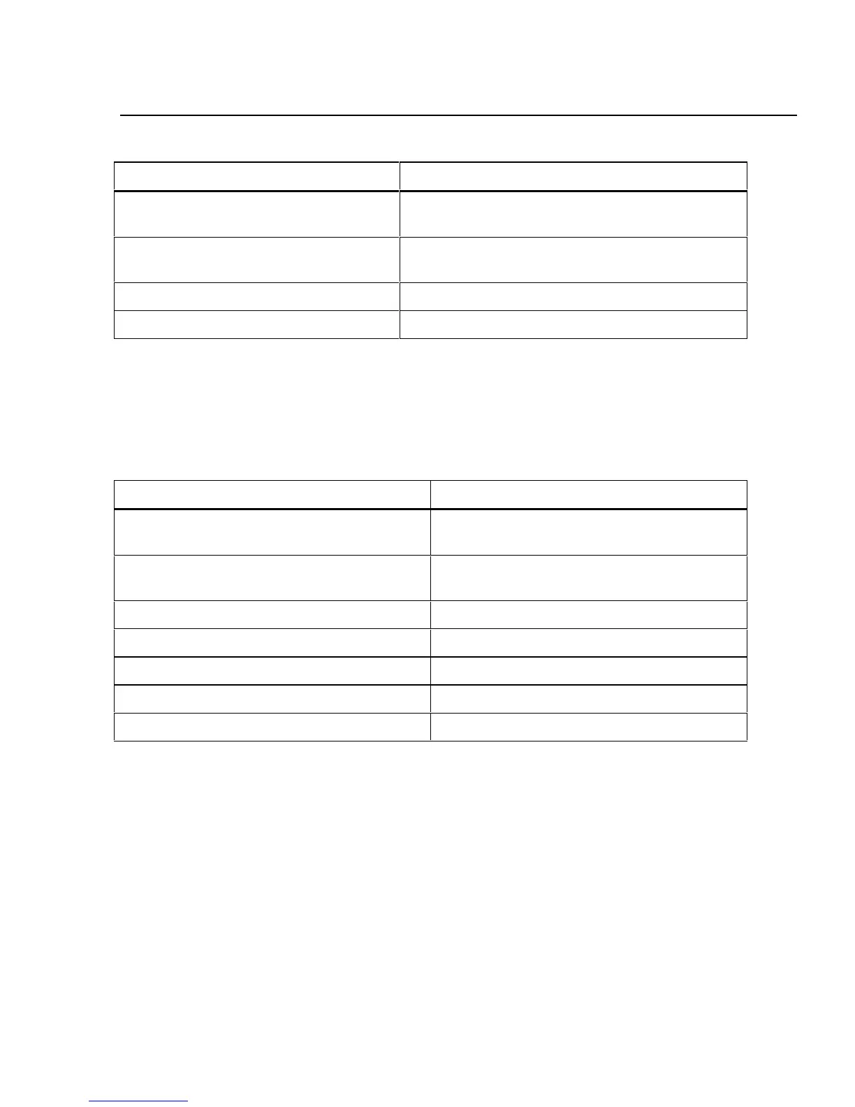
Table A-3. 2640A/2645A DIGITAL I/O Specification (cont)
Specification Characteristic
Output Voltage - TTL Logical Zero 0.8V maximum for an I out of -1.0 mA (1 LSTTL
load)
Output Voltage - TTL Logical One 3.8V minimum for an I out of 0.05 mA (1 LSTTL
load)
Output Voltage - Non-TTL Load Zero 1.8V maximum for an Iout of -20 mA
Output Voltage - Non-TTL Load One 3.25V maximum for an Iout of -50 mA
Trigger In A-7.
Table A-4 provides a summary of the Trigger In specifications. The Trigger In
input is located on the ALARM/TRIGGER I/O connector, terminals TI and GND.
Table A-4. 2640A/2645A Trigger In (TI) Specification
Specification Characteristic
Logical High - Trigger not set Minimum: 2.0V
Maximum: 7.0V
Logical Low - Trigger set Minimum: -0.6V
Maximum: +0.8V
Compatibility TTL or Contact Closure
Isolation None (dc coupled)
Minimum Pulse Width 5 µs
Maximum Frequency Nominal 400 Hz
Repeatability 3 ms