2640A/2645A NetDAQ
Users Manual
6-20
4-Wire Resistance Accuracy Test (2640A) 6-19.
Ensure that the Accuracy Tests (above) have been completed before performing
this test on the 2640A.
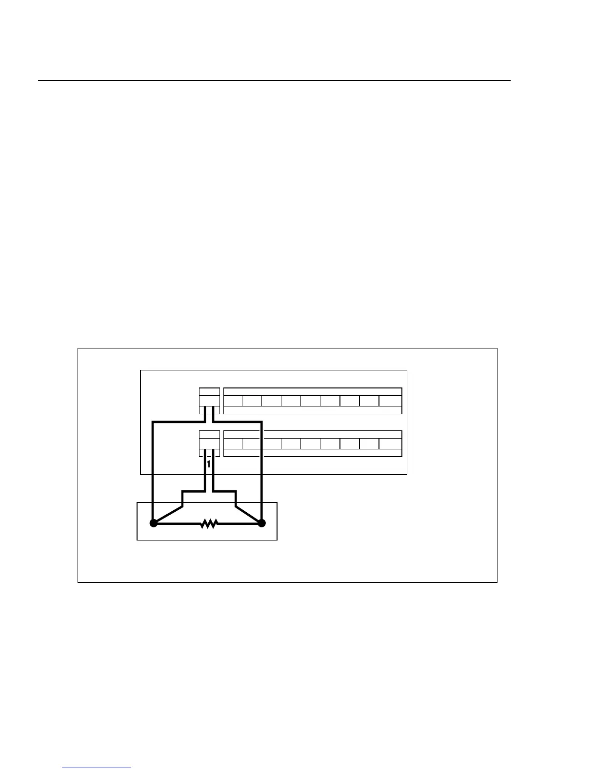
1. Connect the Resistance Source to Channels 1 and 11 Remove the
Universal Input Module from the instrument and connect a cable from the
Decade Resistance Source to the Universal Input Module terminals for
channel 1 (Sense) and channel 11 (Source) as shown in Figure 6-4. Reinstall
the Universal Input Module. You may also use the 5700A resistance
calibration output instead of the Decade Resistance Source. Tables are
provided for both connections. Refer to Figure 6-5 for the 5700A 4-wire
connections.
2. Configure Channel 1 for Resistance In NetDAQ Logger, configure channel
1 for Ohms-4W, 300 range. (See “Configuring Analog Channel Functions" in
Chapter 3 of this manual.)
3. Open Spy Window Select the Spy command from the Utilities menu. Select
analog channel 01. Click OK to open the Spy window.
1211 13 14 15 16 17 18 19 20
21 345678910
SOURCE
(4-WIRE)
SENSE
(4-WIRE)
H L H LH LH LH LH LH LH LH LH L
H L H LH LH LH LH LH LH LH LH L
4-Wire (4W) Connection
5700A, Decade Resistance Box
or
DIN/IEC75/RTD
Input
Module
Figure 6-4. 4-Wire Connections to the Universal Input Module (Resistor)