2640A/2645A NetDAQ
Users Manual
2-20
Rear Panel Controls 2-23.
The rear panel has a single control: the power switch (Figure 2-10). The power
switch controls both ac and dc power inputs.
Power Switch
Applies AC and/or DC
power to the instrument.
Figure 2-10. Rear Panel Controls
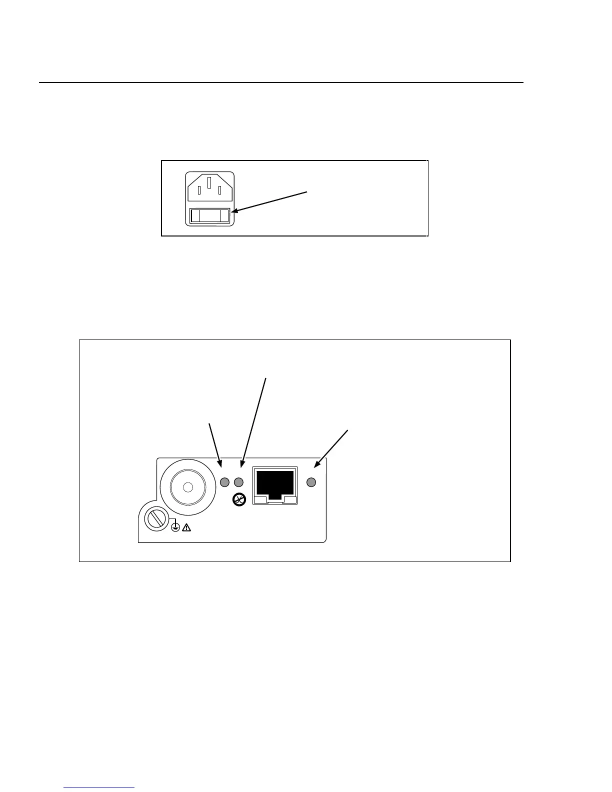
Rear Panel Indicators 2-24.
The rear panel has three LED indicators for the Ethernet adapter (Figure 2-11).
ETHERNET
NOT FOR CONNECTION TO
PUBLIC TELEPHONE SYSTEMS
XMT
RCV LK
Amber LED for instrument
Ethernet status: 10BaseT, LED
on for connection with hub;
10Base2, LED blinks for data
collisions.
Red LED blinks for instrument
receiving Ethernet data.
Red LED blinks for
instrument transmitting
Ethernet data.
Figure 2-11. Rear Panel Indicators