Preparing for Operation
Instrument Preparation
2
2-15
External Trigger Wiring for a Group Instrument 2-19.
External Trigger Wiring for a group instrument refers to the triggering
configuration in which you connect the Master TO (Trigger Out) line to each
Slave TI (Trigger In) line and provide a common connection to the GND line for
each instrument. This configuration provides improved synchronization of the
group instrument when the scanning intervals are 1 second or less.
Figure 2-7 shows a typical wiring connection for a group instrument. Use
NetDAQ Logger to configure a group instrument as described in Chapter 3 of this
manual.
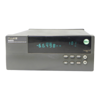
Controls and Indicators 2-20.
The front panel provides a display and a set of control keys; the rear panel
provides the power switch and Ethernet status indicators. See Figures 1-2 through
1-4 for an overall view of front and rear panels, and "Front Panel Operating
Procedures" later in this chapter for procedures that use the front and rear panel
controls and indicators.