2640A/2645A NetDAQ
Users Manual
1-6
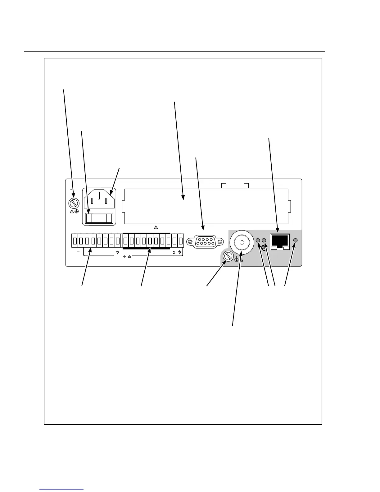
Serial Port.
ALARM/TRIGGER I/O
Connector.
MA (Master Alarm)
output is logic low when
any channel is in alarm;
TO (Trigger Output)
output is logic low for
nominal 125
µ
s at the
start of any scan; TI
(Trigger Input) input
logic low triggers
scanning; DC PWR (dc
volts input) input is 9 to
16V dc to power the
instrument.
DIGITAL I/O
Connector.
Alarm outputs (logic
low for a channel in
alarm) and general
purpose I/O (terminals
0 to 7); totalizer input,
and GND.
Universal Input Module.
Directly wires 20 analog inputs
(Channels 1 to 20) without need
for external signal conditioning.
Ground Terminal.
Connects mainframe to ground.
AC Power Connector.
Connects to any line
source of 107 to 264 volts
ac (50/60 Hz).
Power Switch.
Applies power to the
instrument (ac or dc
operation).
Ground Terminal.
Use for 50-ohm
termination ground
lug.
+
WARNING: TO AVOID ELECTRICAL SHOCK, DISCONNECT LINE CORD BEFORE REMOVING COVER
9-16V
DC PWR
DIGITAL I/O
MA TO TI 0 1 2 3 4 5 6 7
+30V
ALARM/TRIGGER I/O
ETHERNET
NOT FOR CONNECTION TO
PUBLIC TELEPHONE SYSTEMS
MEETS VFG 243 / 1991
OVERVOLTAGE CATEGORY II PER IEC 1010-1
SERIAL PORT
MODEL: 2640A / 41A 2645A / 46A
ON / OFF
XMT
RCV LK
107-264V
50/60 Hz
15VA
Ethernet 10BaseT
Connector.
A RJ-45 connector that
interfaces the instrument with
a 10BaseT Twisted-Pair
Ethernet network. The
instrument automatically
selects the active 10Base2 or
10BaseT connector.
Ethernet Indicators.
XMT (transmit) blinks
red for instrument
Ethernet transmissions;
RCV (receive) blinks
red for any Ethernet
activity on the network;
LK (link) lights amber
when the Ethernet
interface is active for
the Twisted-Pair
connection, and blinks
for a data collision for
the coaxial connection.
Ethernet 10Base2
Connector.
A BNC-type connector that
interfaces the instrument
with a 10Base2 coax
network. The instrument
automatically selects the
active 10Base2 or 10BaseT
connector.
Figure 1-4. 2640A/2645A Rear Panel