2640A/2645A NetDAQ
Users Manual
A-6
Trigger Out A-8.
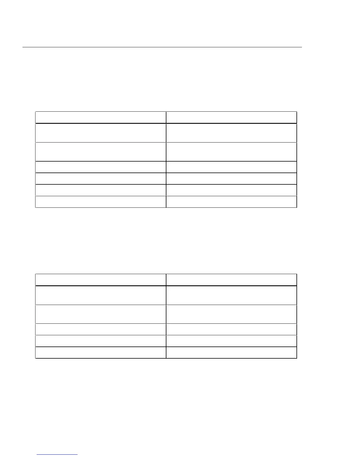
Table A-5 provides a summary of the Trigger Out specifications. The Trigger Out
output is located on the ALARM/TRIGGER I/O connector, terminals TO and
GND.
Table A-5. 2640A/2645A Trigger Out (TO) Specification
Specification Characteristic
TTL Logical Zero - Trigger Out Set 0.8V maximum for an Iout of -1.0 mA (1 LSTTL
load)
TTL Logical One - Trigger Out Not Set 3.8V minimum for an Iout of 0.05 mA (1 LSTTL
load)
Non-TTL Logical Zero - Trigger Out Set 1.8V maximum for an Iout of -20 mA
Non-TTL Logical One - Trigger Out Not Set 3.25V maximum for an Iout of -50 mA
Pulse Duration (Logic Low) 125 µs
Isolation None
Master Alarm A-9.
Table A-6 provides a summary of the Master Alarm specifications. The Master
Alarm output is located on the ALARM/TRIGGER I/O connector, terminals MA
and GND.
Table A-6. 2640A/2645A Master Alarm (MA) Specification
Specification Characteristic
TTL Logical Zero - Master Alarm Set 0.8V maximum for an Iout of -1.0 mA (1 LSTTL
load)
TTL Logical One - Master Alarm Not Set 3.8V minimum for an Iout of 0.05 mA (1 LSTTL
load)
Non-TTL Logical Zero - Master Alarm Set 1.8V maximum for an Iout of -20 mA
Non-TTL Logical One - Master Alarm Not Set 3.25V maximum for an Iout of -50 mA
Isolation None