Using Trend Link for Fluke
Getting the Right Look for Your Trend Link Chart
5
5-19
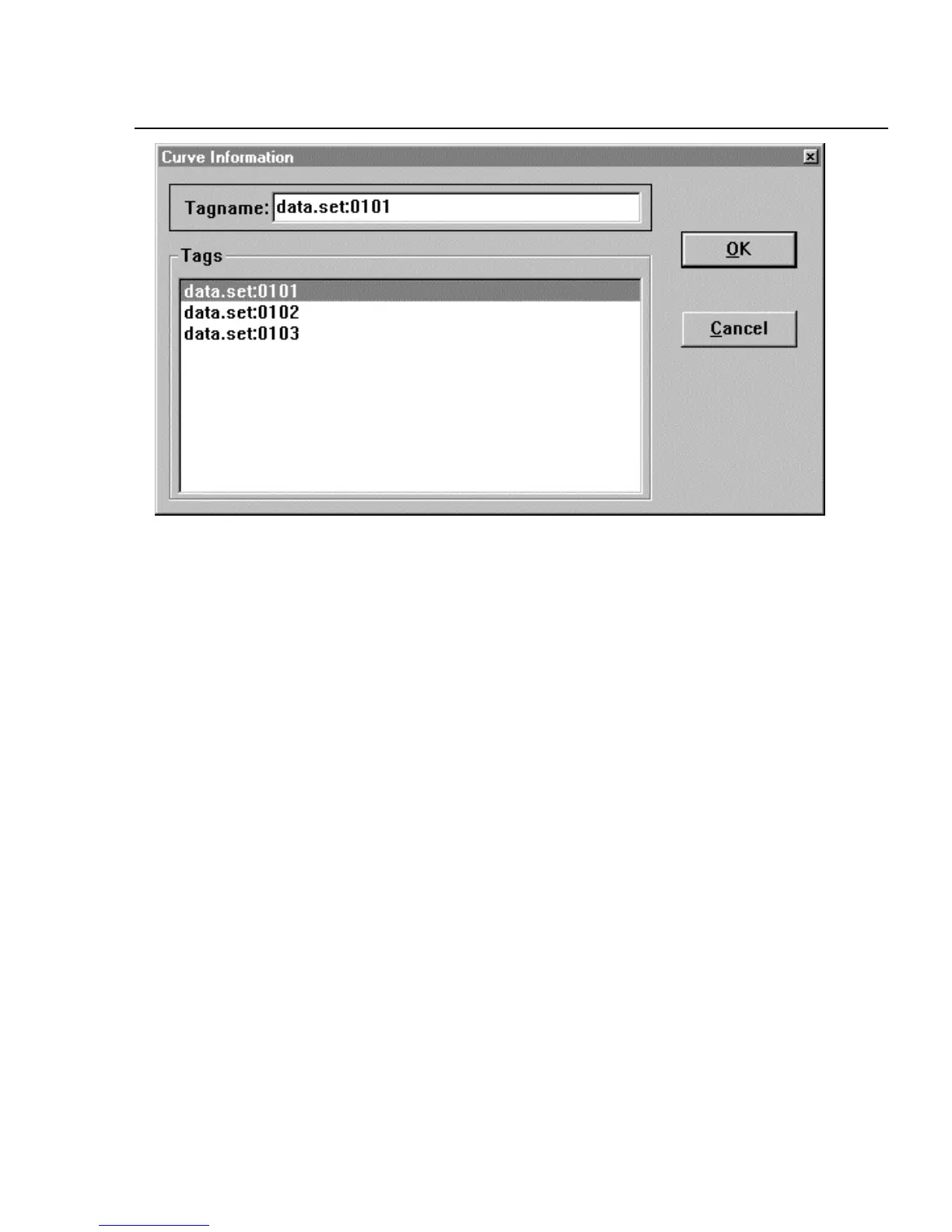
ds135s.bmp
2. Click on the desired curve listed in the Tags box, which will then appear in
the Tagname box. Click OK to open the Curve Parameters box (below). (You
can also open this dialog box directly by double-clicking the Curve icon.)