23
Source Assignment
In the left side of the Web-based Control screen, click to select [Router System Settings -
Source Assignment] in the menu tree to display the settings page..
This page allows you to assign physical inputs to logical input channels.
Source Name
In the left side of the Web-based Control screen, click to select [Router System Settings] -
[Source Name] in the menu tree to display the settings page.
This page allows you to change source names displayed on Remote Controllers or other
devices.
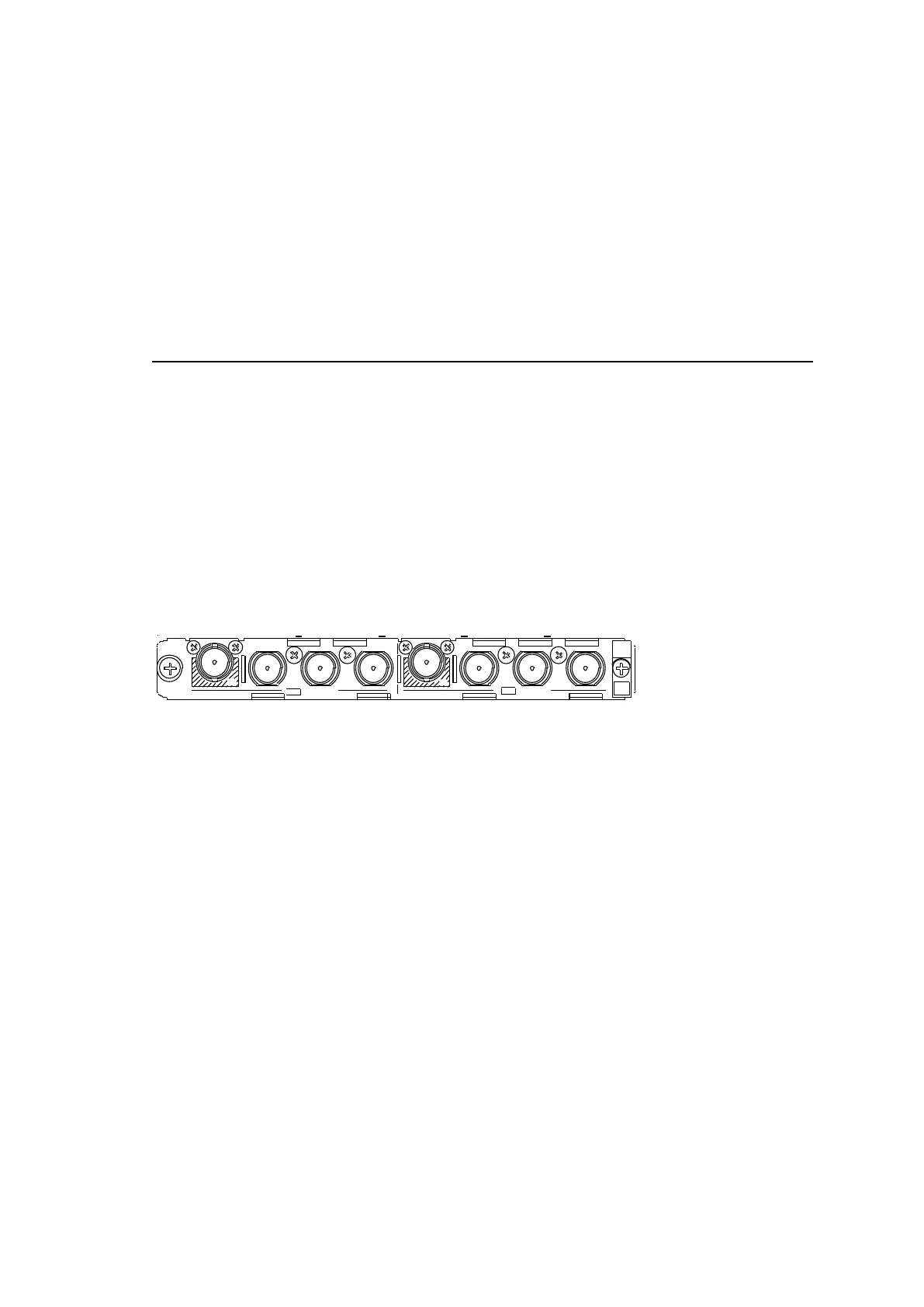
2-4-5. MFR-8SDOGB
The MFR-8SDOGB is an SDI output card that accepts 12G- and 3G-SDI signals and
supports Gearbox feature in which video signal conversions between 12G-SDI and Quad
Link 3G-SDI, and between 2SI and SQD are available.
► See Sec. 7. “Gearbox Feature (MFR-8SDIGB/8SDOGB).”
The following output combinations are available:
12G-SDI signal: 2
3G-SDI signal: 8
12G-SDI signal: 1 and 3G-SDI signal: 4
Up to 8 cards can be installed into Slot No. 09 to 16.
► See Sec. 2-1-1. "Matrix Size Chart."
1
A
1
B
1
C
12G / 3G-SDI
1
D
2
A
2
B
2
C
12G / 3G-SDI
2
D
BNC x 8 outputs (12G/3G-SDI)
Set up output signals in the Web-based Control Software as shown below.
Gearbox settings
In the left side of the Web-based Control screen, click to select [(Main Unit Settings) -
Gearbox Settings] in the menu tree to display the settings page.
This page allows you to set Gearbox input and output signals, lock mode and delay.
Destination Assignment
Open the [Web-based Control: Router System Settings - Destination Assignment page].
This page allows you to assign physical outputs to logical output channels.
Destination Name
Open the [Web-based Control: Router System Settings - Destination Name page].
This page allows you to change destination names displayed on Remote Controllers.