45
3-4-2. Synchronous Crosspoints Switching
1) to 3) Configure the system as described in Sec. 3-4-1.
4) Configure channel link settings:
Open the Re-Entry page and set the menu page as shown below.
* Physical destination channels must be assigned to these logical destination channels
on the MFR-3000.
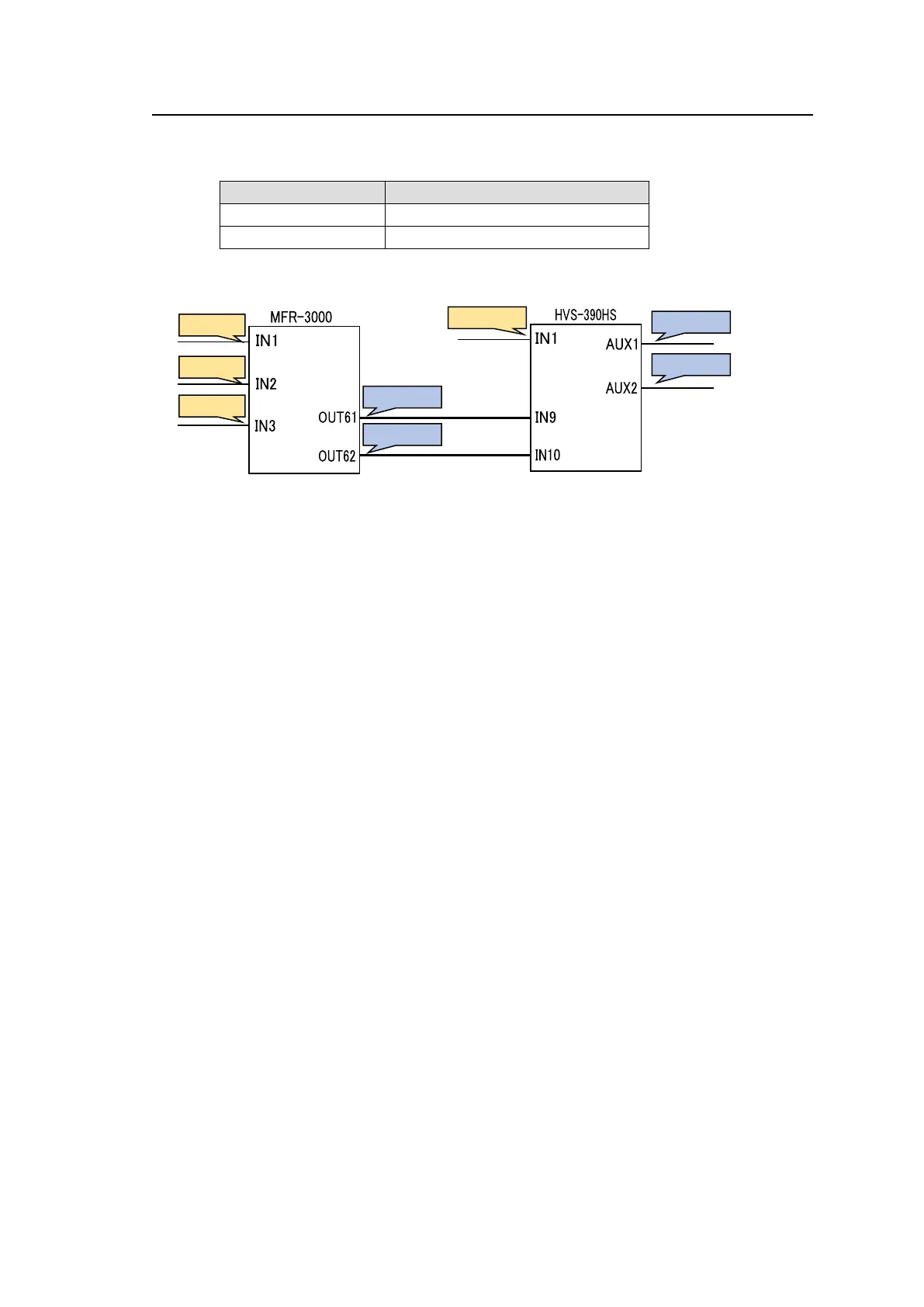
5) Assign logical source and destination channels on the MFR-3000 to input channels and
AUX buses on the switcher.
<AUX bus assignments>
a) Open the Destination Assignment page.
b) Select HVS(AUX) under Select Table.
c) Set Level to 1.
d) Assign AUX1 to DST 129.
e) Assign AUX2 to DST 130.
<Input channel assignments>
a) Open the Source Assignment page.
b) Select HVS(AUX) under Select Table.
c) Set Level to 1.
d) Assign IN1 to SRC 129.
After above setup settings are complete:
If SRC 129 is selected for DST 129 on the MFR-3000, IN1 is selected for AUX1 on the
switcher.
If SRC 3 is selected for DST 129 on the MFR-3000, IN9 is selected for AUX1 on the
switcher and SRC 3 is also selected for DST 61 on the MFR-3000.
If IN9 is selected for AUX1 on the switcher, a source assigned to DST 61 is selected for
DST 129 on the MFR-3000
If IN10 is selected for AUX2 on the switcher, , a source assigned to DST 62 is selected
for DST 130 on the MFR-3000
* Note that destination channels to which physical channels are assigned (DST 61 and
DST 62 in the example above) on the MFR-3000 cannot select source channels to which
the switcher input channels are assigned (SRC 129 in the example above).
* If an AUX crosspoint is switched on the switcher by the Synchronous Crosspoints
switching and it is not listed in Re-Entry page, the AUX crosspoint returns to the previous
state.