14
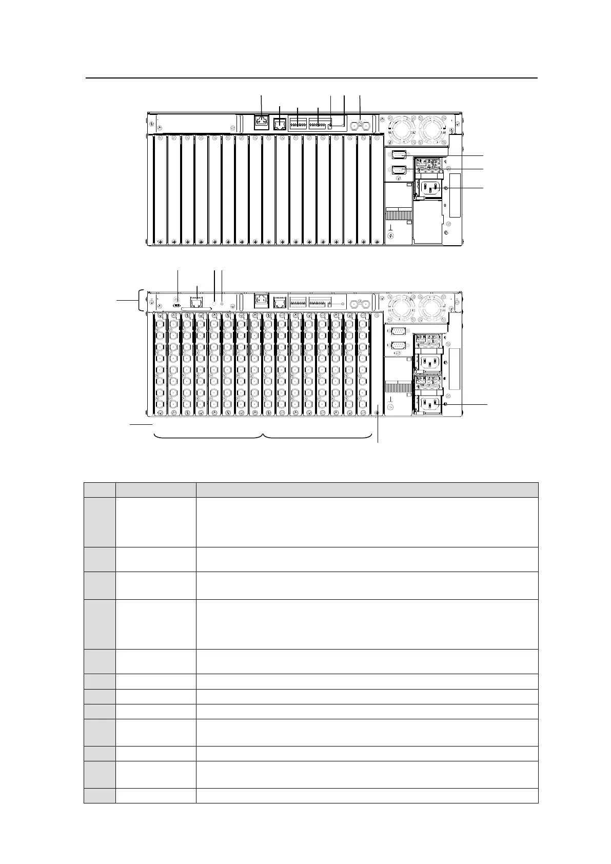
2-3. MFR-3000 Rear Panel
91 23 4 56 7 8 12 3 45 6 78
INPUT OUTPUT
SERIAL
ALARM
REF IN
SET
SLOT
OUTPUTINPUT
98765432187654321
OFF
ON
MFR-LAN1PC-LAN
R
A
T
I
N
G
L
A
B
E
L
A
C
1
0
0
-
2
4
0
V
5
0
/
6
0
H
z
I
N
A
C
1
0
0
-
2
4
0
V
5
0
/
6
0
H
z
I
N
PS2
PS1
SLOT
91 23 4 56 7 812 3 45 6 78
INPUT
ON
SET
POWER
OFF
MFR-LAN2
IN
1
1
2
3
4
5
6
7
8
IN
1
2
3
4
5
6
7
8
IN
1
2
3
4
5
6
7
8
IN
1
2
3
4
5
6
7
8
IN
1
2
3
4
5
6
7
8
IN
1
2
3
4
5
6
7
8
IN
1
2
3
4
5
6
7
8
IN
1
2
3
4
5
6
7
8
1
1
2
3
4
5
6
7
8
1
2
3
4
5
6
7
8
1
2
3
4
5
6
7
8
1
2
3
4
5
6
7
8
1
2
3
4
5
6
7
8
1
2
3
4
5
6
7
8
1
2
3
4
5
6
7
8
1
2
3
4
5
6
7
8
2 3 4 5 6 7 8 2 3 4 5 6 7 8
OUT OUT OUT OUT OUT OUT OUT OUT
OUTPUT
SERIAL
ALARM
MFR-30CPU
ACTIVE
REF IN
SET
SLOT
OUTPUTINPUT
98765432187654321
OFF
ON
MFR-LAN1PC-LAN
R
A
T
I
N
G
L
A
B
E
L
A
C
1
0
0
-
2
4
0
V
5
0
/
6
0
H
z
I
N
A
C
1
0
0
-
2
4
0
V
5
0
/
6
0
H
z
I
N
PS2
PS1
SLOT
* The above figure shows an MFR-3000 with MFR-8SDI and MFR-8SDO cards installed.
Ethernet ports for connection to MFR Remote Control Units and MFR-GPI
(10/100/1000BASE-T, RJ-45)
(1) For MFR-3000
(2) For MFR-30CPU
Ethernet ports for connection to PC or other external unit
(10/100BASE-TX RJ-45)
Used for alarm output
► See Sec. 2-3-1. "Interfaces."
Used for control via a serial interface. RS-232C or RS-422 selectable.
► See Sec. 2-3-1. "Interfaces."
The SERIAL connector is set to RS-422 as factory default. Consult your
FOR-A reseller if you wish to change the setting.
Used to connect Power Supply Unit 1 (standard equipment) to an AC
power source
Used to connect Power Supply Unit 2 (optional) to an AC power source
Used for installing input cards
Used for installing output cards
Used to input a reference signal (BB or Tri-level sync)
(with loop-through. Terminate with 75Ω terminator, if unused.)
(1) Input card power switches
(2) Output card power switches
01 02 03 04 05 06 07 08 09 10 11 12 13 14 15 16