118
7. Serial / LAN Command Control
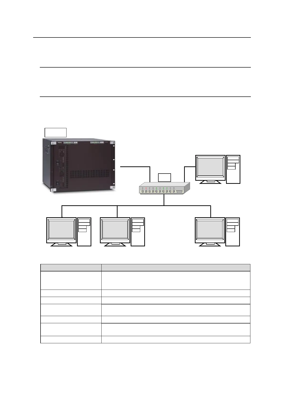
Up to 20 external devices can be connected to an MFR Main Unit (including MFR-GPI serial ports)
through LAN or serial interface.
7-1. Serial Interface
Crosspoint switchover and tally output can be controlled via the SERIAL ports on the MFR
Series main unit or MFR GPI.
7-2. LAN Interface
The MFR Series main unit is able to connect to a third-party automatic control system via the
RJ-45 port (PC-LAN port). The TCP/IP communication protocol is supported. The control PC will
be the Client, and the MFR Series main unit will be the Server.
Basic specifications
Primary LAN (PC-LAN CPU1) default IP address: 192.168.1.12
Secondary LAN (PC-LAN CPU2) default IP address: 192.168.1.13 *
(Subnet Mask: 255.255.255.0)
Setting range: 49152 to 65534 (Default: 23)
Wait before sending next command (Resend if the Echo is not
returned.)
TCP/IP, Control PC: Client, MFR-3232: Server
Crosspoint Remote Control using ASCII code.
Crosspoint Remote Control protocol
* When a redundant CPU is configured, a client should connect to both LAN ports (PC-LAN CPU1 and
PC-LAN CPU2) and send commands to the ports respectively. When the system functions normally, the
secondary port (PC-LAN CPU2) do not respond to commands. But if an error occurs in the CPU1 system,
the secondary port will take over the primary port and repond to commands.

 Loading...


