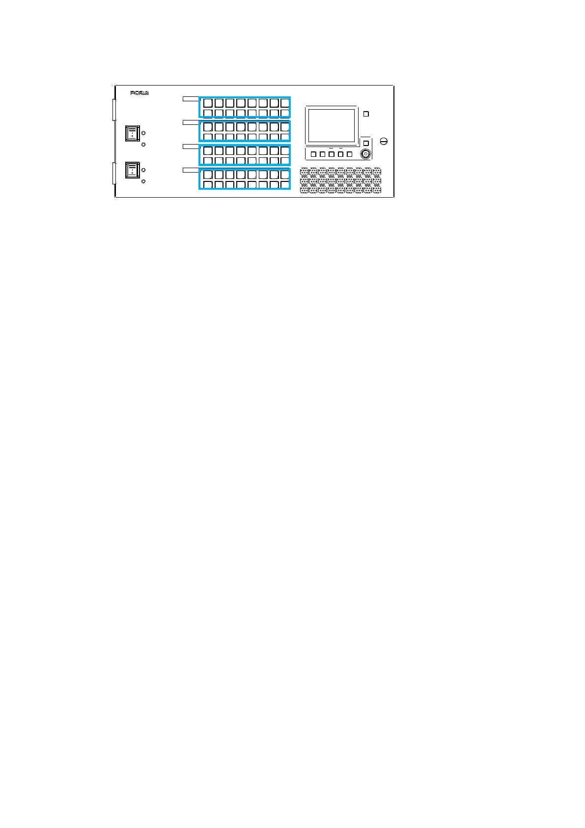
EasyManuals Logo

FOR-A MFR-3000 User Manual

FOR-A MFR-3000
157 pages
To Next Page IconTo Next Page
To Previous Page IconTo Previous Page
Page #48 background imageLoading...
Page #48 background image
48
3. System Configuration Example
3-1. Basic Configuration
The block diagram below shows an example of the basic MFR routing system that consists of an
MFR-5000, Remote Unit and the Web-based Control accessed from a computer.
Make sure to connect both MFR-LANs (CPU1) and (CPU2) to a LAN respectively for CPU
redundancy. Their LAN connections must be separated from the network segment of PC-LAN
and other devices. (Default IP addresses (Net mask: 255.255.255.0) are used in the
configuration example below.)
LAN Port Settings
Port
RU Front Panel
Web-based
Control
Sec. in Web
Control Manual
MFR-39RUA: See sec. 5-4-4.
MFR-39RU: See sec. 5-6-1.
MFR-18RU/18RUA: See sec. 5-8-1 and 5-8-2
Other RUs: See sec. 5-10-1 and 5-10-2.
RU Settings
page
6-3
---
MU Settings
page
5-2
MFR-39RUA: See sec. 5-4-4(display only).
MFR-39RU: See sec. 5-6-3(display only).
MFR-18RU/18RUA: See sec. 5-8-1 (display
only).
Other RUs: See sec. 5-10-1 (display only).
Network
Settings page
4-1-7
MFR-LAN(CPU1)
MFR-LAN(CPU2)
MFR-xxRU
SDI/ AES
SDI/ AES
REF IN
MFR-5000
IN1
|
|
|
|
I
|
|
I
|
|
IN128
OUT1
|
|
|
|
I
|
I
|
|
I
OUT128
Ethernet Hub (MFR-LAN)
Ethernet Hub (PC-LAN)
PC
MFR Web-based
Control
BB
VIDEO(SDI)
LAN (MFR-LAN)
LAN (PC LAN)
LAN port label indications have
been changed.
TO RU >> MFR-LAN (CPU1, 2)
TO PC >> PC-LAN
192.168.1.XX
192.168.1.12
192.168.1.11
192.168.1.10
192.168.1.XX
PC-LAN1
PC-LAN2
192.168.1.13

Table of Contents

Other manuals for FOR-A MFR-3000

Questions and Answers:

Question and Answer IconNeed help?

Do you have a question about the FOR-A MFR-3000 and is the answer not in the manual?

FOR-A MFR-3000 Specifications

General IconGeneral
BrandFOR-A
ModelMFR-3000
CategorySwitch
LanguageEnglish

Related product manuals