57
5-1-3. CHOP Function
The CHOP function allows you to alternate 2 images to compare the images.
Enabling the CHOP function
(1) Press one of 2 source buttons (source A) to compare the images.
(2) While holding down the source button, press and release another source button (source
B).
Source A and B images alternate.
5-1-4. Crosspoint Switching Using TAKE Function
Crosspoint switching using the Take function is available by the front panel that is assigned
Take.
The Take function enables crosspoint switching by the TAKE button.
The Take function has 2 modes that can be assigned to different front panel respectively. To
select the Take mode, select Preset or Direct under Take Mode in in the [Web-based
Control: RU Settings page].
Preset mode
Press the TAKE button to enable Take, and select crosspoints, then press the TAKE button
to switch crosspoints.
Direct mode
The Take function is always enabled. Select crosspoints, then press the TAKE button to
switch crosspoints.
Ex.1: To use the TAKE button assigned to Preset mode
Press the TAKE button.
The take function will be enabled,
and the button will be highlighted.
Select a crosspoint by selecting a destination
button and source button.
The selected buttons will blink.
* To switch multiple crosspoints, repeat the procedure.
After completing the crosspoint selection, press the blinking TAKE button to
switch the crosspoint/s.
In multiple crosspoint switching, the last set of destination and source buttons will
be highlighted.
Once a crosspoint switch has been completed, the TAKE button preset mode will be
disabled. The button will return to direct mode.
To switch crosspoints in the preset mode again, repeat the procedure from step 1.
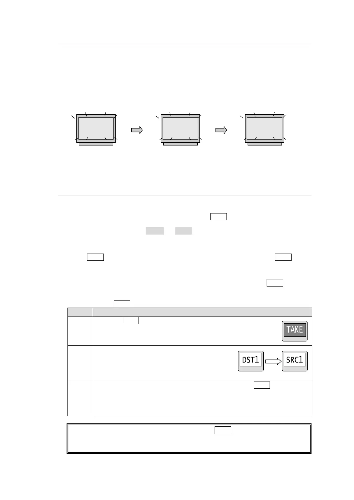
Press source button A.
→ Source A is output.
Holding down source button A,
press source button B.
→ Source B is output.
Release source button B.
→ Source A is output.