EasyManua.ls Logo

FOR-A MFR-3000 - Interfaces

FOR-A MFR-3000
98 pages
Print Icon
To Next Page IconTo Next Page
To Previous Page IconTo Previous Page
Loading...
16
2-3-1. Interfaces
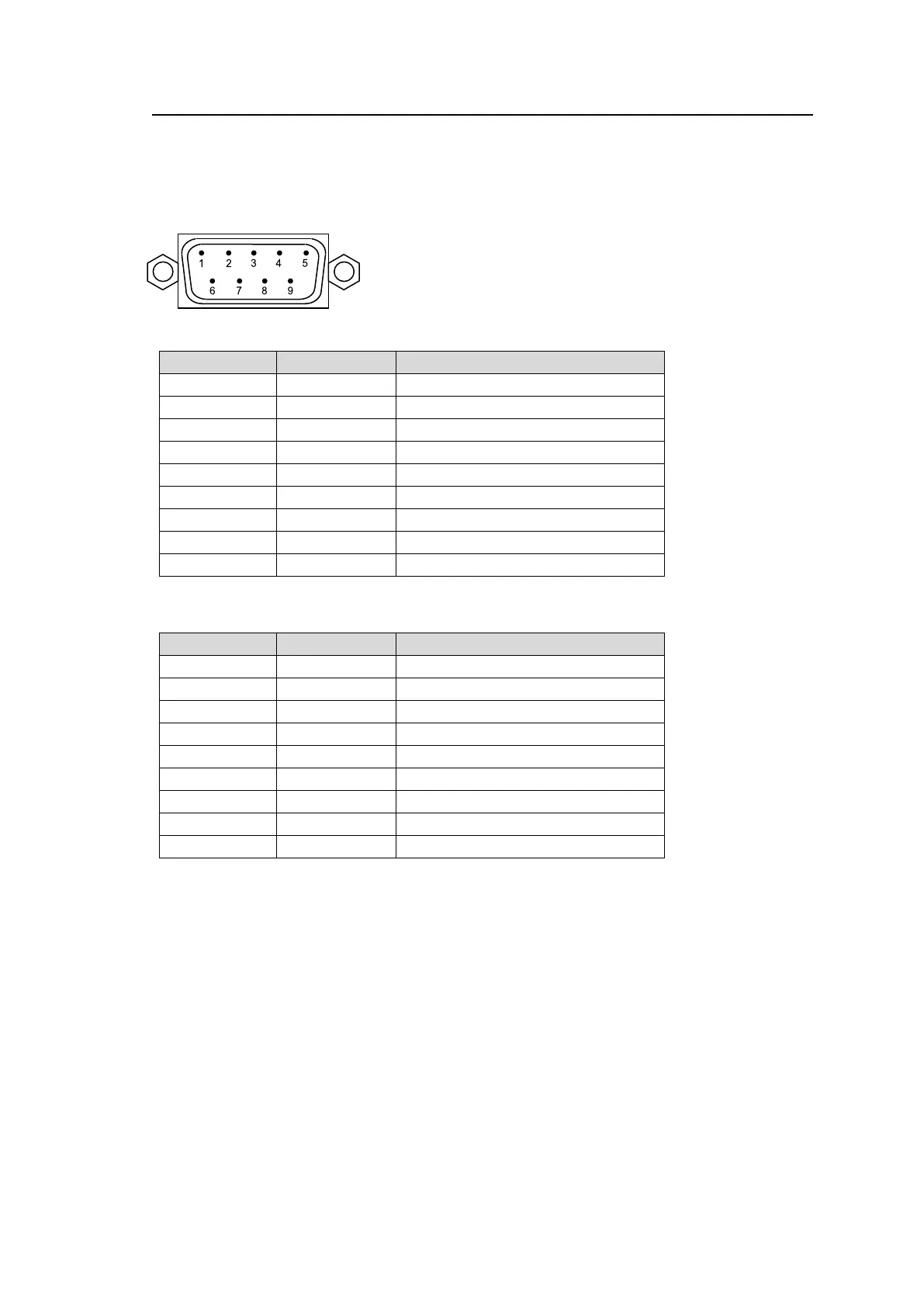
SERIAL Connector (9-pin D-sub, male)
RS-232C or 422 interface can be selected via the CPU card DIP switches.
(See Sec. 2-3-4. "Changing the Interface from RS-422 to RS-232C."
RS-422 connector pin assignment (Factory default settings)
Pin No.
Signal Name
Description
1
FG
Frame Ground
2
T-
Transmit data (-)
3
R+
Receive data (+)
4
SG
Signal Ground
5
NC
Unused
6
SG
Signal Ground
7
T+
Transmit data (+)
8
R-
Receive data (-)
9
FG
Frame Ground
* The maximum cable length is 100 m.
RS-232C Connector Pin Assignments
Pin No.
Signal Name
Description
1
NC
Not used
2
RxD
Received Data
3
TxD
Transmitted Data
4
DTR
Data Terminal Ready
5
SG
Signal Ground
6
DSR
Data Set Ready
7
RTS
Request To Send
8
CTS
Clear To Send
9
NC
Not used
* The maximum cable length is 10 m.
* DTR/DSR and RTS/CTS are internally connected respectively.
9-pin D-sub, male

Table of Contents

Related product manuals