58
Ex. 2: To use the TAKE button assigned to Direct mode
In Direct mode, the Take function is always
enabled.
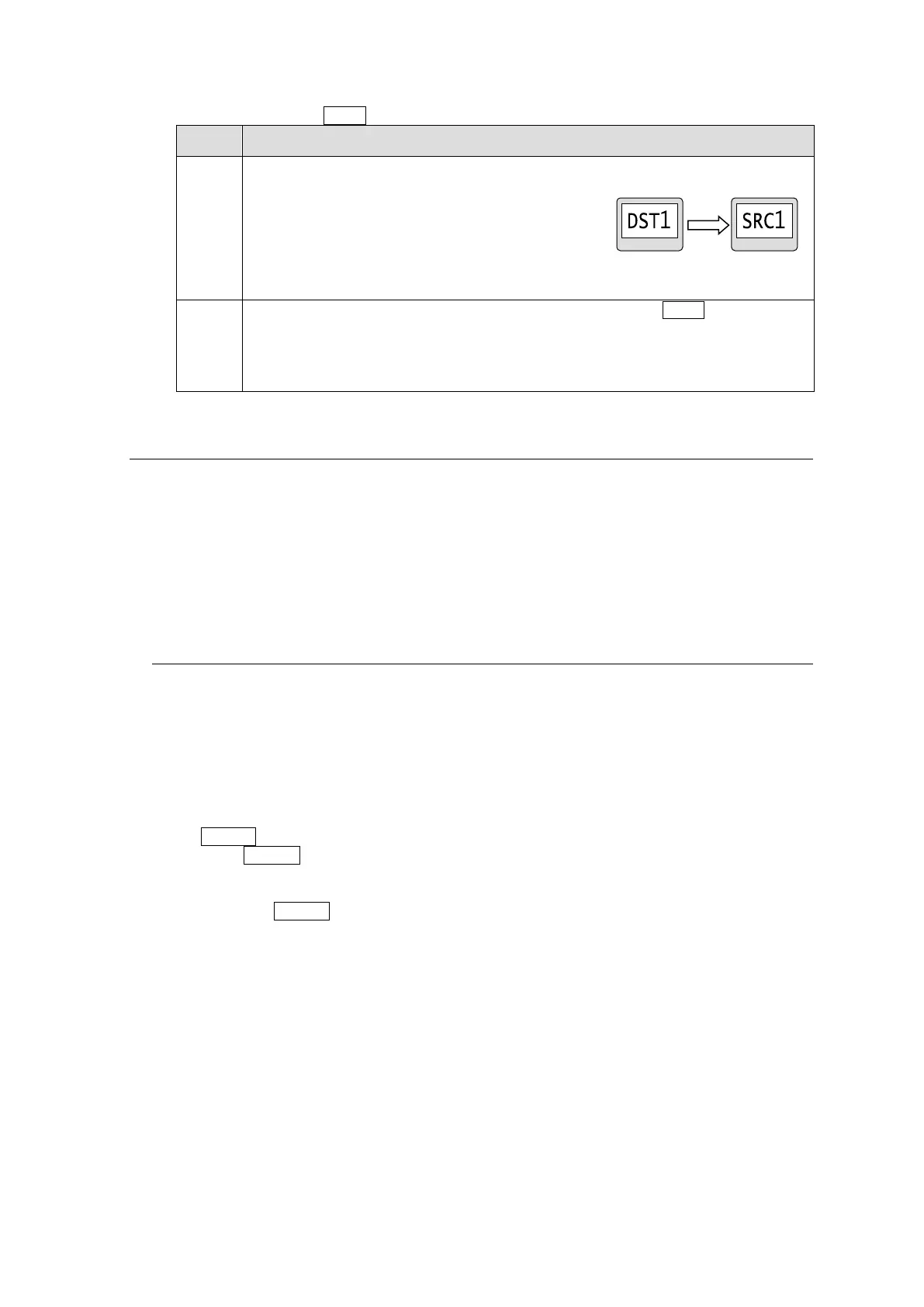
Select a crosspoint by selecting a destination
button and source button.
The selected buttons will blink.
* To switch multiple crosspoints, repeat the procedure.
After completing the crosspoint selection, press the blinking TAKE button to
switch the crosspoint/s.
In multiple crosspoint switching, the last set of destination and source buttons will
be highlighted.
5-2. Simultaneous Crosspoint Switching
The simultaneous crosspoint switching function allows you to simultaneously switch multiple
crosspoints by the press of one button. There are two ways to do so. One is the Salvo function
which performs the switching by recalling the pre-assigned crosspoints. The other is the Take
function which allows you to assign and switch multiple crosspoints simultaneously.
The SALVO crosspoints can be saved to the routing switcher main unit and buttons on the
front panel.
5-2-1. Main Unit Stored Salvos
This type of salvo allows you to store crosspoint data to be simultaneously switched. The
stored data can be recalled from the front panel.
Storing Salvo Data to Main Unit
Salvo data for Main Unit can be stored using the Web-based Control.
► See [Web-based Control: Salvo page]
Executing Salvos
Use a SALVO (MU RECALL) button on the front panel as shown in the procedure below.
(1) Assign a SALVO button on the front panel. Set the salvo for MU RECALL, and select a
Salvo number.
► See Sec. 4-4-4. "Button Assign Menu."
(2) Pressing the SALVO button to executes the salvo. The crosspoints stored to the salvo
number are simultaneously set.