15
Used to insert / remove input / output cards with MFR-3000 powered on.
Used to replace an MFR-30CPU card.
Used to manually activate an installed MFR-30CPU.
Displays the MFR-30CPU status.
Lit: MFR-30CPU is active.
Unlit: MFR-3000 CPU is active.
Flashing: MFR-30CPU manual activation is disabled.
After installing an MFR-30CPU, MFR-LAN 1, MFR-LAN 2 and PC-LAN connectors
must be connected to their respective devices to enable CPU redundancy. MFR-LAN
and PC-LAN must be located on different LAN segments. Do not connect them to
existing LAN networks.
Input /output cards and Slots
8SDI / 8SDIGB: Max. 8 cards
8SDO / 8SDOGB: Max. 8 cards
16MV: Max. 4cards *
8AAO, 8AESO: Max. 8 cards
* Available slot pairs are No. 09-10, 11-12, 13-14, and 15-16.
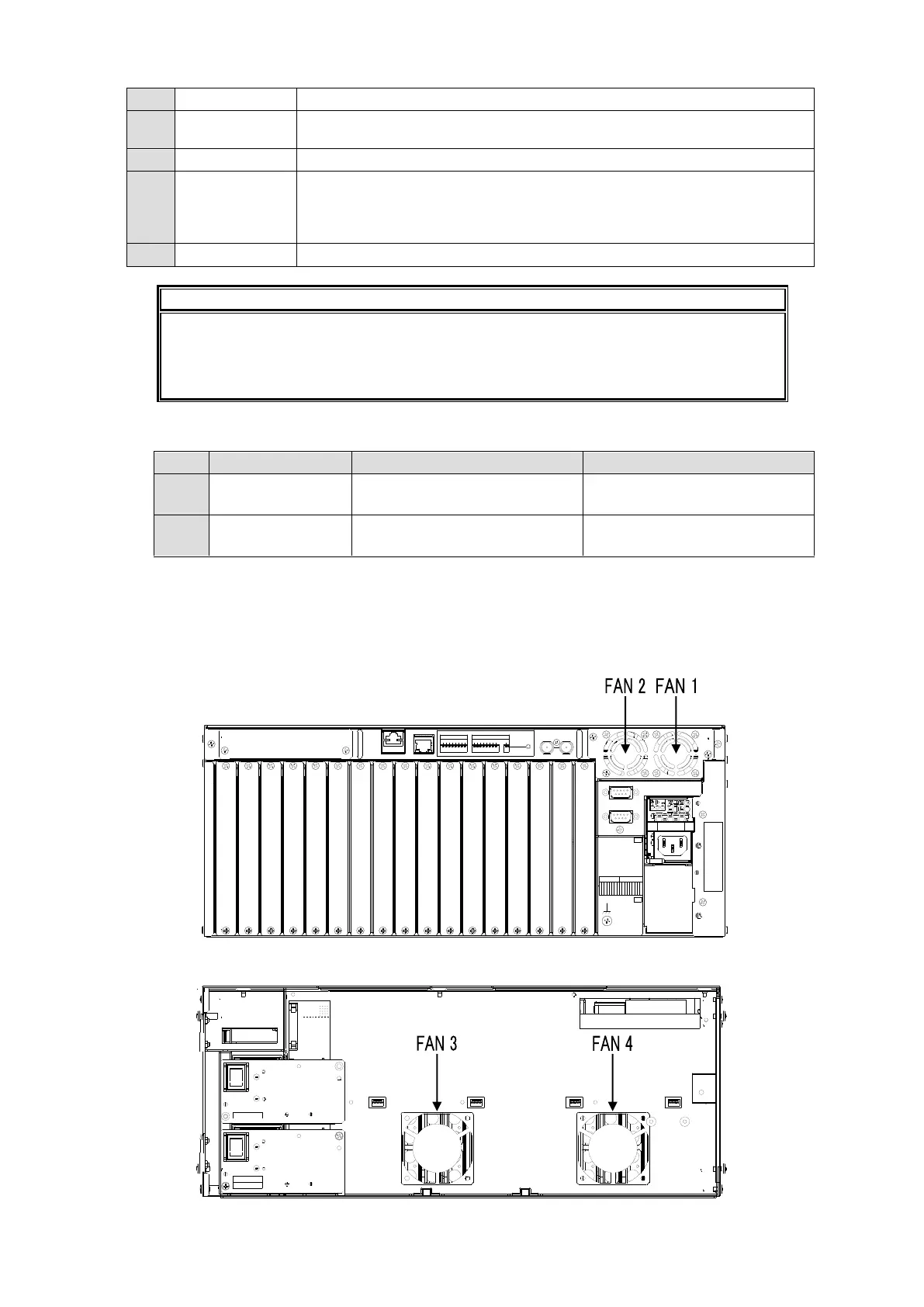
Cooling fans
Four cooling fans are installed in MFR-3000 units: FAN 1 and 2 are on the rear panel and
FAN 3 and 4 are on the front panel as shown below.
Rear Panel
Front panel inside
91 23 4 56 7 8 12 3 45 6 78
INPUT OUTPUT
SERIAL
ALARM
REF IN
SET
SLOT
OUTPUTINPUT
98765432187654321
OFF
ON
MFR-LAN1PC-LAN
R
A
T
I
N
G
L
A
B
E
L
A
C
1
0
0
-
2
4
0
V
5
0
/
6
0
H
z
I
N
A
C
1
0
0
-
2
4
0
V
5
0
/
6
0
H
z
I
N
PS2
PS1
SLOT