132
8-2. Available Conversions
The following input conversions are available on MFR-16SDIGB cards
0 frame + ** (H)
1 frame + Delay (H)
Line lock
(*1)(*2)
Genlock
The following output conversions are available on MFR-16SDOGB cards
0 frame + ** (H)
1 frame + 0H
1 frame + Delay (H)
Line lock
(*1)(*2)
Genlock
1 frame + 0H
1 frame + Delay (H)
(*1) SDI signal input to the A connector is used as reference. When Line Lock is selected on MFR-16SDOGB
cards, video signals are synchronized by inputting signals to all four channels in gearboxes.
(*2) Available only on Gearboxes 1 and 3.
(*3) Delay (H) and Total Delay (H) indicate amount of delay and their settings correspond to the following
adjustable ranges.
(*4) If Total Delay (frame) is set to “0 frame” for both gearboxes, the different Total Delay (H) setting is
available for the gearboxes.
If Total Delay (frame) is set to “1 frame” for either one or both gearboxes, the same Total Delay (H)
setting is required for the gearboxes: 1 frame + 0H or 1frame + Delay (H).
8-3. Conversion Settings
In the Web GUI, specify the Gearbox input and output formats and assign input/output physical
channels to logical channels. Use Link Settings that allow simultaneous 4-channel operation
and facilitate crosspoint switches.
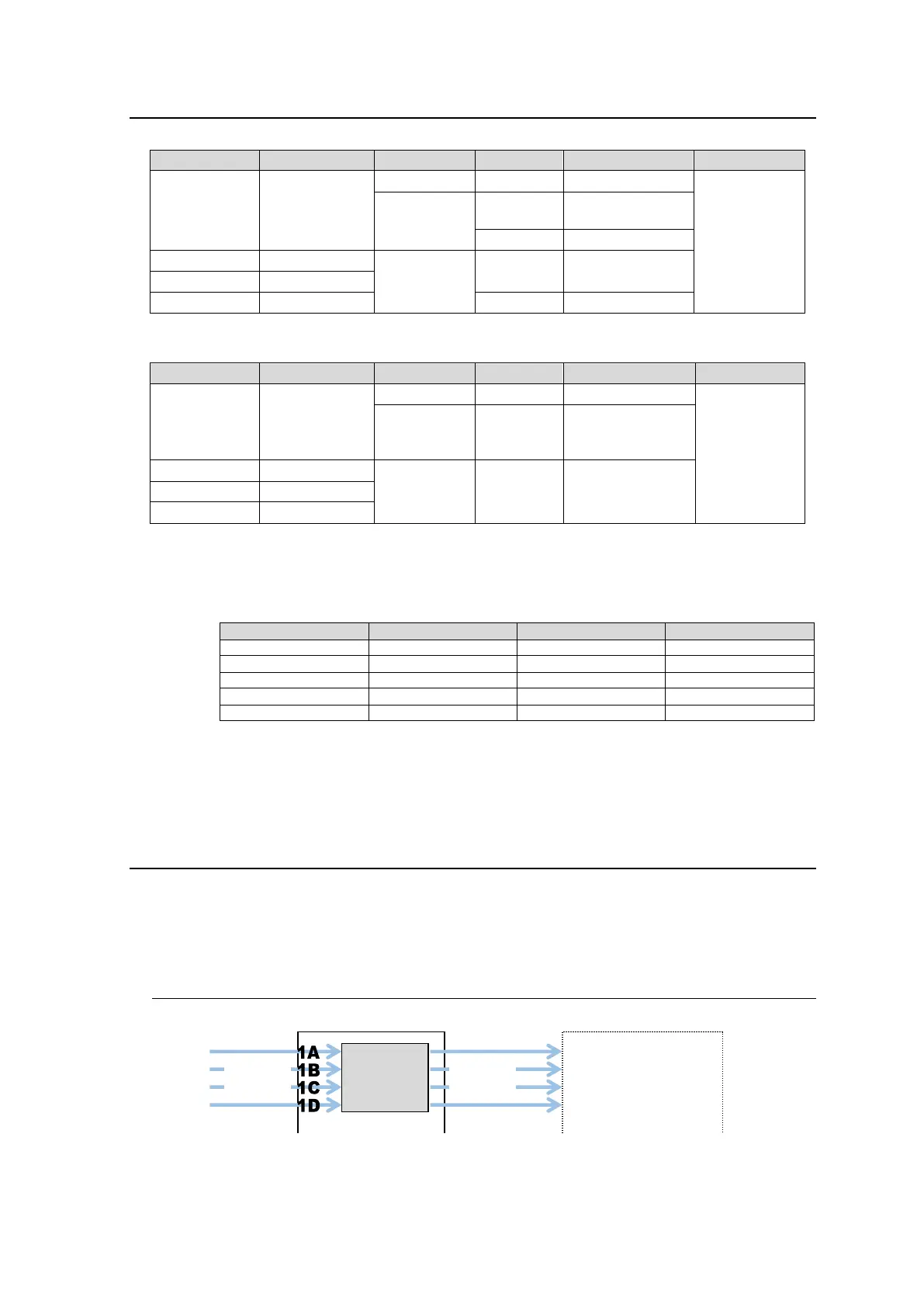
8-3-1. Converting 3G SQD Input to 2SI (MFR-16SDIGB)

 Loading...


