20
2-3-4. Changing the Interface from RS-422 to RS-232C
Note that internal switch settings should only be performed by qualified technical
personnel.
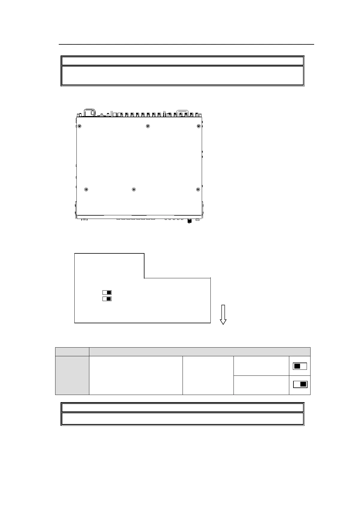
(1) Remove the 6 screws on the MFR-3000 top panel to remove the panel.
(2) The MAIN card factory default settings are as shown below.
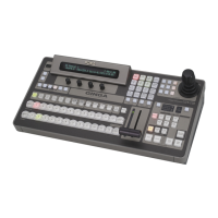
Switch settings
Used to select RS-232C or
RS-422. Make your selection
referring to the right figures. Both
switches must be set the same.
Do not change other switches