60
5-3. Lock
Function operation and crosspoint changes can be disabled by the Lock function.
LOCK Function
The Lock function is a function that inhibits the use of function buttons or crosspoint changes.
There are three types of Lock functions.
5-3-1. LOCK LOCAL
The Lock Local function inhibits operation of buttons and menus that change the source
channel or sets or executes Take switching on the unit that enabled the Lock function.
(Selecting destination channels is not inhibited.)
This function is used in protecting the system from unintended operation.
Enabling LOCK LOCAL
(1) Assign LOCK LOCAL to a button on the front panel.
► See Sec. 4-4-4. "Button Assign Menu.".
(2) Press the assigned LOCK LOCAL button to enable the Lock Local function.
* Operations are locked for units in black boxes and unlocked for units in white boxes.
Disabling LOCK LOCAL
Press the LOCK LOCAL button again.
On the remote control panel:
LOCK LED is lit green
LOCK LOCAL is highlighted (background of the text illuminates.)
Source and bus button indications are crossed.
To check the LOCK status, press the current destination button.
The MENU display shows the LOCK status (ON or OFF) as shown below.
The LOCK LOCAL button and LOCK LED on the remote control panel flash if any inhibited
operation such as changing the source channel is performed when Lock Local is enabled.
(Only if the LOCK LOCAL button is assigned.)
LOCK LOCAL can be issued only on Remote Control Units.
DST: 8 [DST8 ]
LK-LOCAL [PANEL LOCK ]
DST: 8 [DST8 ]
LK-OFF [NOT LOCKED ]
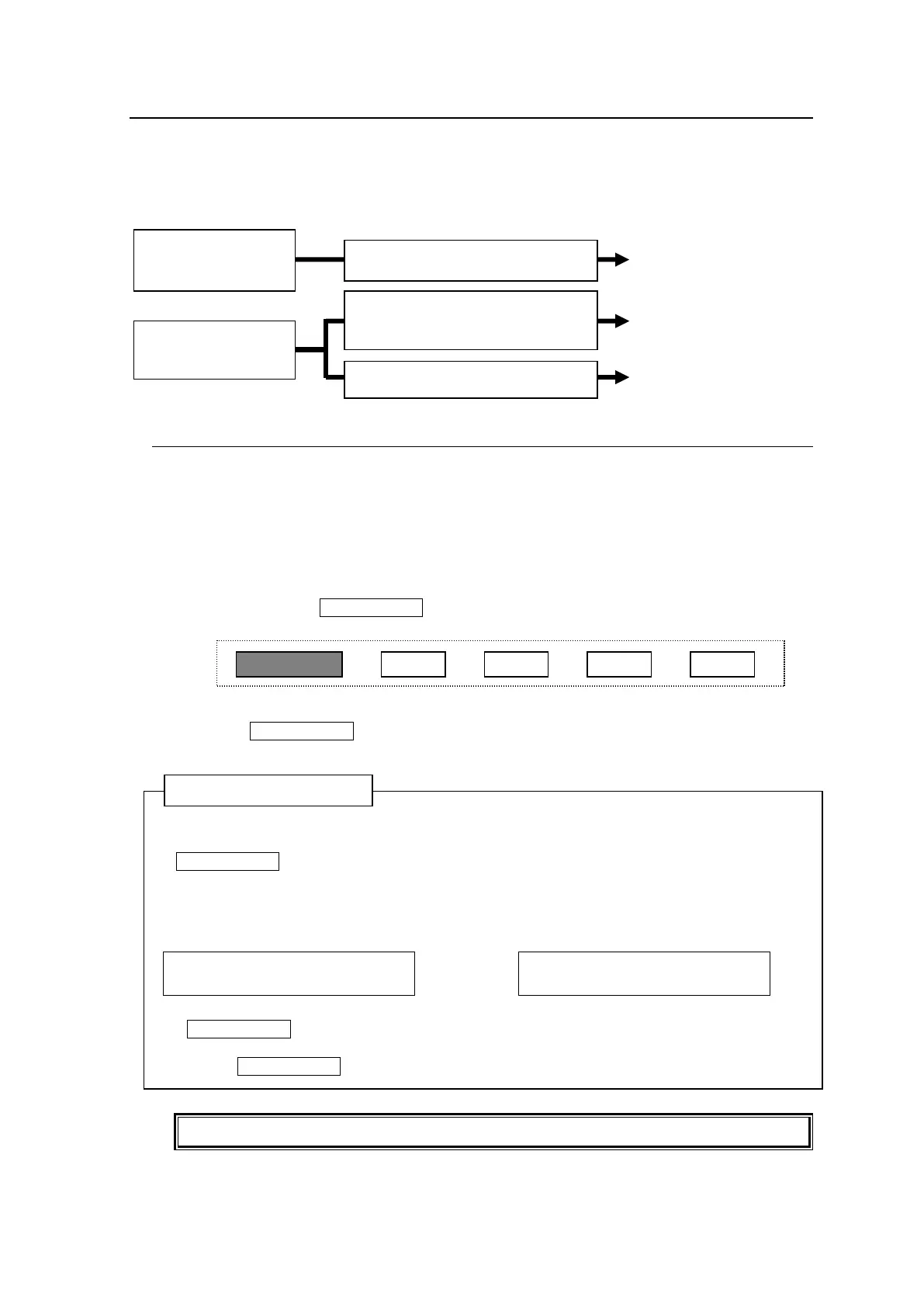
Inhibits source
channel and function
button operation
Inhibits operation on own unit
Inhibits the specific
destination channel
related operation
Inhibits operation from other units
Inhibits operation form other groups.
Inhibits operation for all units