QUANTUM™ LX EVAPORATOR CONTROL PANEL
OPERATION
090.610-O (MAR 2016)
Page 10
CHECKING THE AC POWER
Interface Panel
▯ Ensure that the Control Power switch is in the
OFF position.
▯ Energize the 120 Volt circuit at its source.
▯ Using a DVM, measure the voltage at the AC
power terminal strip. Ensure that you read ap-
proximately 120 VAC between Hot and Neutral,
and Hot and Ground. There must not be voltage
between Neutral and Ground.
▯ Once the incoming voltage has been veried,
turn the Control Power switch to ON.
▯ On the enclosure door, and watch the Quantum™
LX controller (on the backside of the door). You
should notice various LED’s blinking or ashing.
▯ Watch the display on the front of the door. Af-
ter a short period of time, you should notice the
display showing a boot sequence. Various text
messages will be shown as it proceeds with the
boot-up process. When nished, a screen similar
to the following image should be visible:
▯ If the panel has reached the point of showing the
above screen, the boot process was successful.
Turn OFF the Control Power switch, and De-en-
ergize the 120 Volt circuit at its source.
▯ If the panel does not reach to the point of show-
ing the above screen, then troubleshooting will
be required. Refer to end of this guide entitled
Troubleshooting.
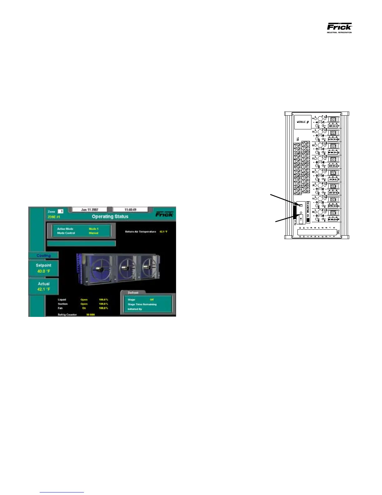
Remote Panel(s)
▯ Unlike the Interface Panel, the Remote panels
do not have an external power switch. Instead,
the enclosure will contain two HOA (Hand-Off
Automatic Modules). These modules allow the
technician to override control signals, by manu-
ally energizing components. An example of one
of these modules is shown here:
▯ Notice in the above pictorial, there is a Red pow-
er OFF tab, and a black power ON plunger. These
items are located on a circuit breaker for each of
the two HOA modules. Together, they act as the
Control Power switch.
▯ Push each of the Red power OFF tabs down. The
Black power ON plunger should pop up. If the
plunger does not pop up, then the power was
already off. Do this to both HOA modules.
▯ Energize the 120 Volt circuit at its source.
▯ Using a DVM, measure the voltage at the AC
power terminals (1, 2 and PE). Ensure that you
read approximately 120 VAC between Hot and
Neutral, and Hot and Ground. There must not be
voltage between Neutral and Ground.
▯ Once the incoming voltage has been veried,
push in the Black power ON plungers of both
HOA modules.
▯ To the right of the HOA modules are several I/O
boards. There will be at least one Digital board
(recognizable by the plug-in I/O modules), and
one Analog board. Inspect all boards for the
presence of ashing, blinking or steadily lit
LED’s. If LED’s are lit on all boards, then power
has been properly applied.
▯ If LED’s are not lit on all boards, then refer to the
section entitled Troubleshooting.