QUANTUM™ LX EVAPORATOR CONTROL PANEL
OPERATION
090.610-O (MAR 2016)
Page 17
VERIFYING COMMUNICATIONS
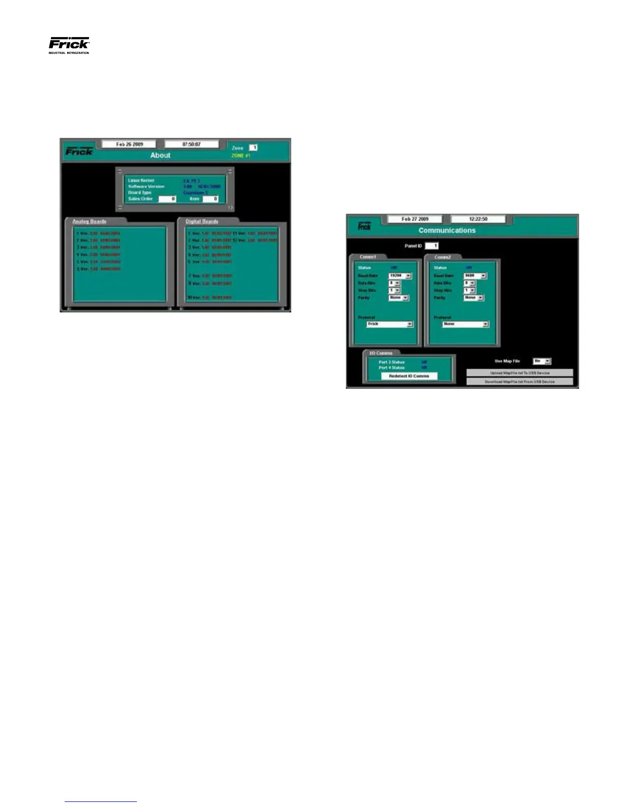
The rst step in verifying communications is to view what I/O
boards have been detected by the Interface Panel. This infor-
mation will appear on the About screen, shown here:
Review the information that is shown in the Analog and Digital
Board areas of the screen. Compare what is shown against
what is actually installed.
NOTE: This screen does not update (refresh) automati-
cally. To see any new or different information that may
occur, you must access a different screen, then come
back to this one to see any new data.
The analog board area of the screen can list up to the ten
possible analog boards that are allowed, and they are listed
in a single column. In the digital board area, you will notice
that there are two columns. The left hand column represents
Panels 1 through 5 (and digital boards 1 – 10), and the right
hand column represents Panels 6 – 10 (and Digital boards 1 -
10). Refer to the Zone Conguration Chart and the Evaporator
System Communications Wiring Diagram for clarication.
Compare what is displayed here with what is actually installed
in your system. If a board is physically installed in a Remote
Panel, yet does not show up on this screen, then nd the Panel
that the board is located in, and visually check the RX and TX
LED’s on the board. These LEDs should be ashing. The RX
LED will be ashing much faster than the TX LED, but neither
should be off completely, as this indicates a potential wiring
problem.
Start by verifying that the boards within Remote Panel 1 are
correctly being detected. Then move on to the next panel, and
so on, for each of the two potential communications branches
(Comm. 3 and Comm. 4). If Remote Panel 1 shows correctly,
but there is a problem with Remote Panel 2, then do nothing
with the wiring up to and including Panel 1. Inspect instead
Panel 2 for proper communications polarity and connections.
A good indication that you have wires backwards (reversed)
would be that the RX LED is on solid within the suspect panel.
If wiring WAS found to be incorrect, make the correction, and
then access the Communications screen by selecting Congu-
ration from the Main Menu, then Communications.
On the Communications screen shown above, use the [Tab]
key to select Redetect IO Comms and press [Enter]. This
will cause the Quantum™ LX controller to reinitiate all com-
munications with the system. After Redetecting IO Comms,
wait about 30 seconds, then access the About screen once
again. If the wiring issue has been corrected, the questionable
I/O board should now be listed, and the RX/TX LED’s for that
board should be ashing normally.
If the boards for Remote Panel 2 are now properly detected,
then move on to Panel 3, etc.
When all installed boards have been detected, then the basic
setup is complete. You can now move on to conguring the
system operating parameters.