QUANTUM™ LX EVAPORATOR CONTROL PANEL
OPERATION
090.610-O (MAR 2016)
Page 13
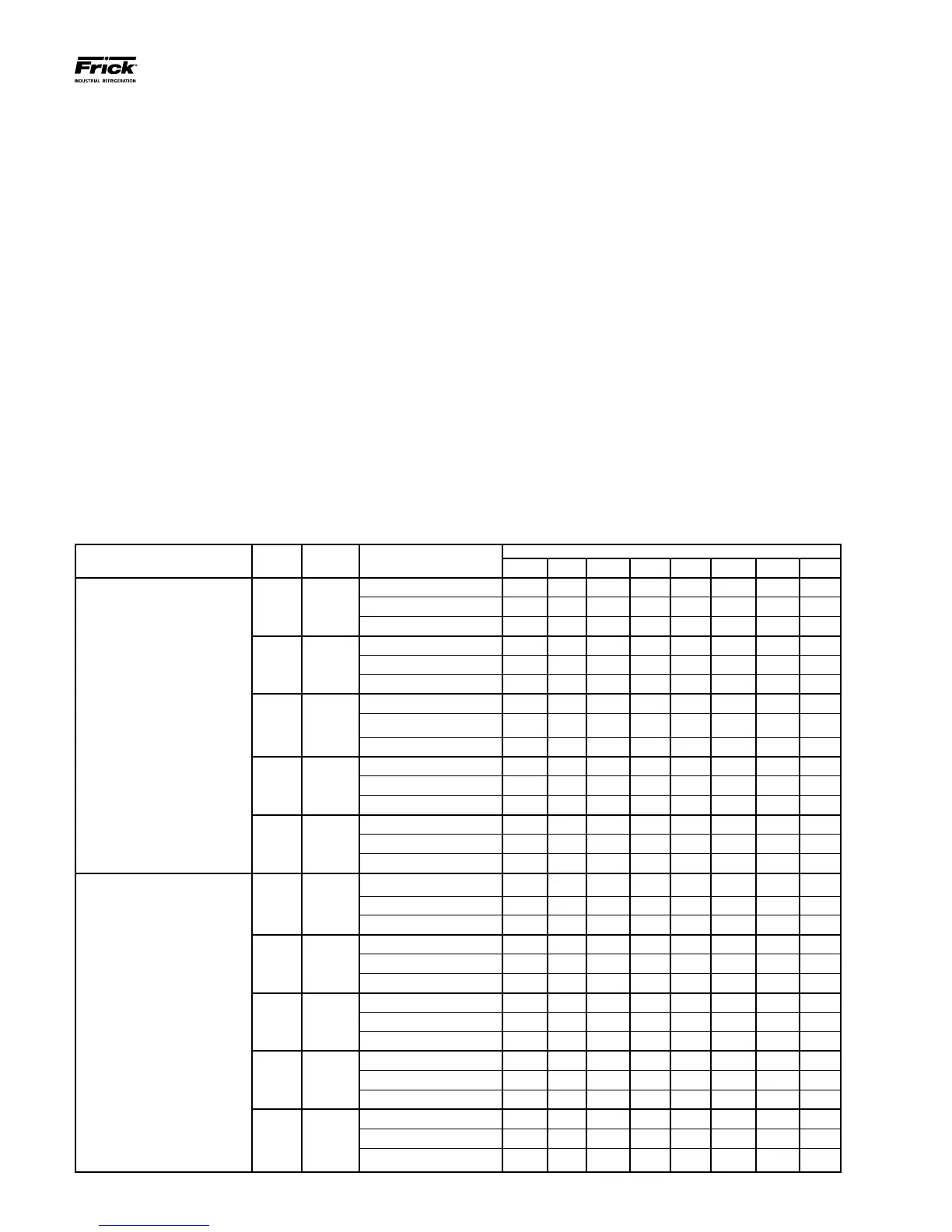
ZONE CONFIGURATION CHART
The following table is to be used to set the System congura-
tion. The following page then shows a pictorial representa-
tion of how this chart applies to a full system. The columns
indicate:
• INTERFACE COMMUNICATIONS PORT
• COMM. 4 – This is an RS-485 serial port physi-
cally located on the Q4 controller, or on the Q5
Interface (within the Operator Interface Panel).
This signal can directly feed all attached Remote
Panels (up to 2000 feet total distance). This port
provides communications to the digital and an-
alog boards within Remote Panels 1 through 5
(zones 1 through 15)
• COMM. 3 - On the Q4 controller, this is an RS-
232 serial port physically located on the Q4 con-
troller (within the Operator Interface Panel). This
signal requires conversion to RS-485 to meet
the distance requirements of the system, so a
converter module has been installed to provide
this conversion (provides up to 2000 feet total
distance). On the Q5 controller, this port is lo-
cated on the Interface board. This port provides
communications to the digital and analog boards
within Remote Panels 6 through 10 (zones 16
through 30)
• PANEL # - This number identies each Remote
Panel as a discrete device, similar to an address.
Each Panel can control up to 3 zones.
• ZONE # - This number identies each individual
zone in the system. It is this value that will ap-
pear on many of the Interface Panel screens to
describe the zone that is being viewed.
• BOARD # - This lists the available analog and
digital boards within each zone.
• DIPSWITCH # - This shows the settings of how
each dipswitch must be congured to recognize
the appropriate I/O board.
INTERFACE
COMMUNICATIONS PORT
PANEL
#
ZONE # BOARD #’s
DIPSWITCH SETTINGS
SW1 SW2 SW3 SW4 SW5 SW6 SW7 SW8
COMM. 4
1 1, 2, 3
Analog Board 1 Off Off Off Off Off Off Off Off
Digital Board 1 On On On On Off On N/A N/A
Digital Board 6 (opt.) Off On Off On Off On N/A N/A
2 4, 5, 6
Analog Board 2 On Off Off Off Off Off Off Off
Digital Board 2 Off On On On Off On N/A N/A
Digital Board 7 (opt.) On Off Off On Off On N/A N/A
3 7, 8, 9
Analog Board 3 Off On Off Off Off Off Off Off
Digital Board 3 On Off On On Off On N/A N/A
Digital Board 8 (opt.) Off Off Off On Off On N/A N/A
4
10, 11,
12
Analog Board 4 On On Off Off Off Off Off Off
Digital Board 4 Off Off On On Off On N/A N/A
Digital Board 9 (opt.) On On On Off Off On N/A N/A
5
13, 14,
15
Analog Board 5 Off Off On Off Off Off Off Off
Digital Board 5 On On Off On Off On N/A N/A
Digital Board 10 (opt.) Off On On Off Off On N/A N/A
COMM. 3
6
16, 17,
18
Analog Board 6 Off Off Off Off Off Off Off Off
Digital Board 11 On On On On Off On N/A N/A
Digital Board 16 (opt.) Off On Off On Off On N/A N/A
7
19, 20,
21
Analog Board 7 On Off Off Off Off Off Off Off
Digital Board 12 Off On On On Off On N/A N/A
Digital Board 17 (opt.) On Off Off On Off On N/A N/A
8
22, 23,
24
Analog Board 8 Off On Off Off Off Off Off Off
Digital Board 13 On Off On On Off On N/A N/A
Digital Board 18 (opt.) Off Off Off On Off On N/A N/A
9
25, 26,
27
Analog Board 9 On On Off Off Off Off Off Off
Digital Board 14 Off Off On On Off On N/A N/A
Digital Board 19 (opt.) On On On Off Off On N/A N/A
10
28, 29,
30
Analog Board 10 Off Off On Off Off Off Off Off
Digital Board 15 On On Off On Off On N/A N/A
Digital Board 20 (opt.) Off On On Off Off On N/A N/A