QUANTUM™ LX EVAPORATOR CONTROL PANEL
OPERATION
090.610-O (MAR 2016)
Page 6
The Operator Interface Panel (we will call it the In-
terface Panel throughout the rest of this guide) is the
central point of the system, whereby all Remote Zone
Interface Panels are attached. It can easily be identi-
ed by the presence of a display screen and a keypad.
The Interface Panel monitors and controls all of the
Remote panels that are attached to it, through RS-
485 serial communications (to be explained later).
The Interface Panel runs the actual program that
provides the control for the entire system. Through
communications, it monitors the status of each
attached Remote Zone Interface Panel, and provides
the necessary control instructions for each Remote
Zone Interface Panel to perform. Additionally, all
setpoints are stored in the Interface Panel.
Status of the entire system may be monitored form
here, and appropriate changes made to system
operation.
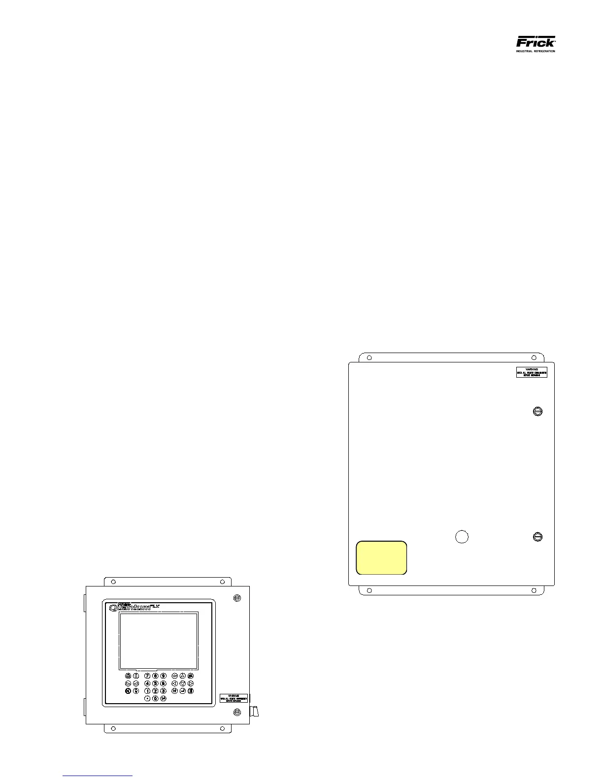
THE REMOTE I/O PANEL
Each complete Evaporator system will have from one
to ten Remote I/O Panels, and each panel is capable
of controlling up to 3 Evaporator zones:
Quantum LX Evaporator
Remote Panel Number: ___________
Notice that there is a yellow sticker on the front
of the door for each Remote I/O Panel. This sticker
will identify the Remote Panel number and the
Zones it will control. This will all be explained in
greater detail later, but it is an important fact to
note.
The Remote Panels do not have a display or keypad. Each
Remote Panel can control three independent Zones. Each
Quantum™ LX Evaporator system can manage up to 10
Remote I/O Panels, providing the ability to control as
many as 30 Evaporator zones.
SETUP DESCRIPTION
The following Setup Guide is meant to assist the installation
technician in making all necessary electrical power, control and
communications connections to a Quantum™ LX Evaporator
system. They will be provided also with the basic information
necessary to login and congure the system. It will then aid in
troubleshooting the system should problems arise. This Guide
will help to ensure:
WIRING
• Location of incoming AC source power to all
panels (Interface and Remote)
• Basic installation guidelines are followed.
• Location, polarity and grounding of
communications wiring.
• Location of all control (I/O) wiring.
• Proper powering up of all panels.
CONFIGURATION
• Logging into the system.
• Verifying communications.
• Conguring the Zones.
• Calibrating sensors.
• Setting up operating Setpoints.
OPERATION
• Setting the operating Mode.
• Verifying the data being returned to the Interface
panel from all remote panels (Zones).
• Checking and clearing of alarms.
• Zone overview
• Ammonia Conguration
IDENTIFYING AN EVAPORATOR SYSTEM
A minimum Evaporator system will include one Operator
Interface Panel and one Remote I/O Panel.
THE OPERATOR INTERFACE PANEL
Each complete Evaporator system will have a single
Operator Interface Panel, as shown below: