QUANTUM™ LX EVAPORATOR CONTROL PANEL
OPERATION
090.610-O (MAR 2016)
Page 12
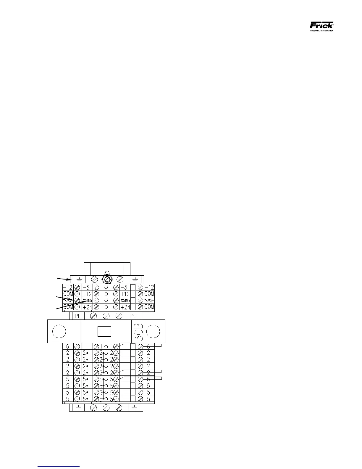
▯ For Q5 units, connect the Comm-3
communications wires directly to the
appropriatly labled Comm-3 terminal
strip.
▯ This should complete the Interface
Panel communications wiring.
▯ This should complete the Interface
Panel communications wiring.
▯ Refer to the Zone Conguration Chart
later in this guide to verify dipswitch
settings.
Remote Panel(s)
Follow the same description for wire stripping as with
the Interface Panel, with the exception that the shield
wire does NOT get trimmed off.
▯ On Evaporator systems with only one Re-
mote Panel, the only communications cable
that you will have is that which comes di-
rectly from the Interface Panel.
▯ Insert the stripped end of the black wire into
the terminal marked TX/RX-, and the white/
clear or red stripped wire into the terminal
marked TX/RX+, and the shield wire into
the Ground terminal as shown (the Ground
terminals may be identied by their Green/
Yellow color).
▯ On Evaporator systems with more than one
Remote panel, the rst Remote panel will
have two communications cables; the rst
will be from the Interface Panel, and the sec-
ond will be going to the next remote panel.
Functionally, it does not matter which cable
is which, as long as the polarity of both is
observed. NOTE: It would be a good idea at
this time however to label each of the two
cables as to where they are going for future
maintenance / troubleshooting use (refer to
the yellow sticker on the front of each Re-
mote Panel for the panel numbers).
▯ Insert the black stripped wires from both
cables to the TX/RX-, and the white/clear or
red stripped wires into the terminal marked
TX/RX+. Both shield wires should be twisted
together, and then taped to prevent them
from touching any live surfaces. The shield
wires DO NOT get connected to any termi-
nals.
▯ Follow this procedure for all Remote Panels,
except for the very last one. This panel will
have only one communications cable (label
it also), which will be coming from the pre-
vious panel. The connections for this cable
are the same as that for a single Remote
Panel, that is, the shield wire must be at-
tached to one of the Ground terminals.
▯
NOTE: Only the last Remote Panel
should have the shield wire grounded
(terminated).