3.4 Programming Mode
3-31
Chapter 3
KEYPAD FUNCTIONS
Basic key operation
To check the status of the I/O signals, set function code E52 to "2" (Full-menu mode) beforehand.
(1) Turn the inverter ON. It automatically enters Running mode. In that mode, press the
key to
switch to Programming mode. The function selection menu appears.
(2) Press the / key to display "I/O Checking" (
$i_o
).
(3) Press the
key to proceed to a list of I/O check items (e.g.
4_00
).
(4) Use the
and keys to select the desired I/O check item, then press the key.
The corresponding I/O check item data appears. For the item
4_00
or
4_01
, using the and
keys switches the display method between the segment display and the hexadecimal display (for I/O).
(Refer to Table 3.4-10 and Table 3.4-11.)
(5) Press the
key to return to the list of I/O check items. Press the key again to return to the
menu.
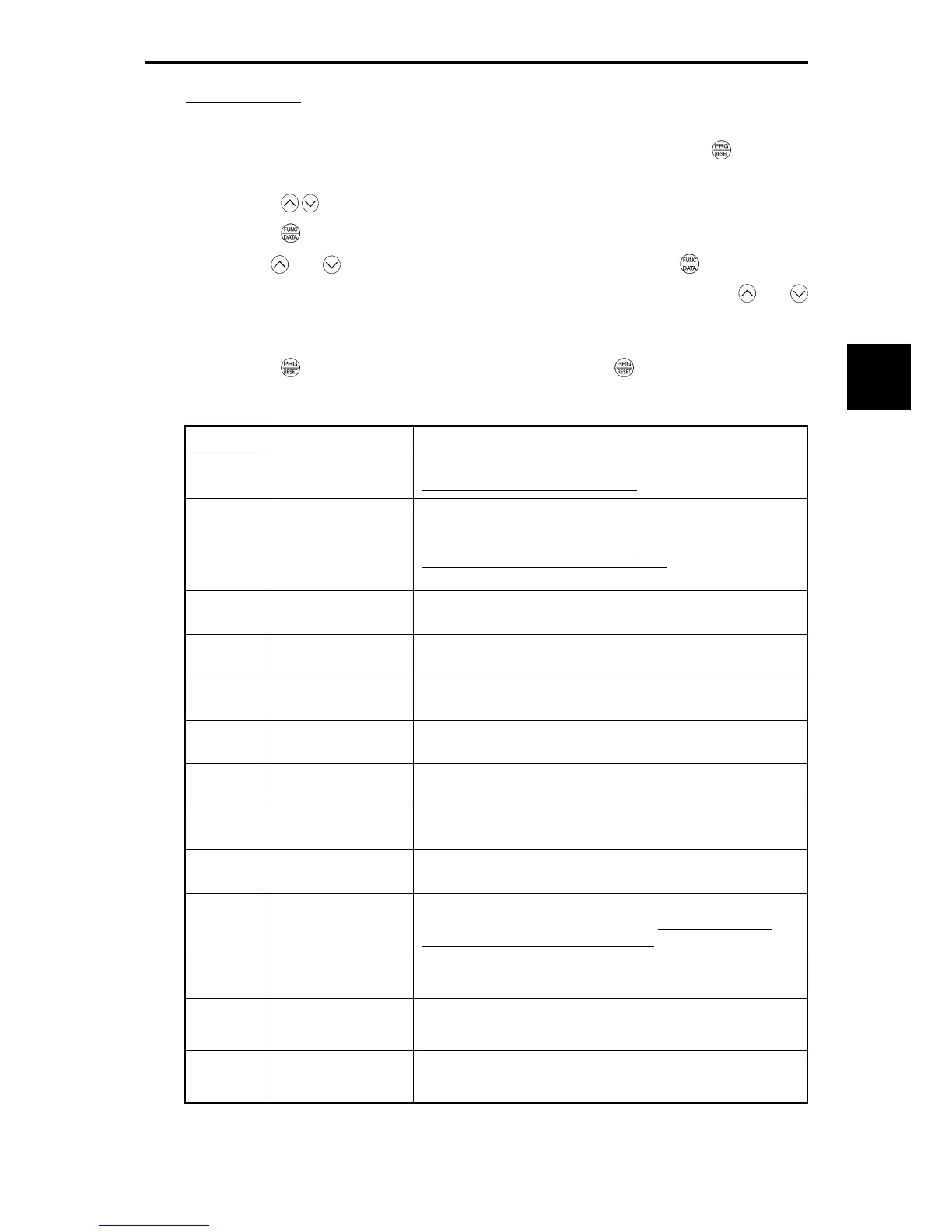
Table 3.4-9 I/O Check Items
LED monitor Item Description
4_00
I/O signals on the
control circuit terminals
Displays the ON/OFF state of the digital I/O terminals. Refer to
"Displaying control I/O signal terminals"
on the next page for details.
4_01
I/O signals on the
control circuit terminals
under communications
control
Shows the ON/OFF state of the digital I/O terminals that received a
command via RS-485 and field path optional communications. Refer to
"Displaying control I/O signal terminals"
and "Displaying control I/O
signal terminals under communications control" on the following pages
for details.
4_02
Input voltage on terminal
[12]
Shows the input voltage on terminal [12] in volts (V).
4_03
Input current on terminal
[C1]
Shows the input current on terminal [C1] in milliamperes (mA).
4_04
Output voltage on
terminal [FMA]
Shows the output voltage on terminal [FMA] in volts (V).
4_05
Output voltage on
terminal [FMP]
Shows the output voltage on terminal [FMP] in volts (V).
4_06
Output frequency on
terminal [FMP]
Shows the output pulse rate per unit of time on terminal [FMP] in (p/s).
4_07
Input voltage on terminal
[V2]
Shows the input voltage on terminal [V2] in volts (V).
4_08
Output current on
terminal [FMA]
Shows the output current on terminal [FMA] in milliamperes (mA).
4_10
Option control circuit
terminal (I/O)
Shows the ON/OFF state of the digital I/O terminals on the digital input
and output interface cards (options). Refer to " Displaying control
circuit terminal on digital I/O interface cards" on page 3-34 for details.
4_11
Terminal [X7]
pulse input monitor
Shows the pulse rate of the pulse train signal on terminal [X7].
4_15
PG pulse rate
(A/B phase signal from
the reference PG)
Shows the pulse rate (kp/s) of the A/B phase signal fed back from the
reference PG. (Shows 1.00 with 1000 p/s.)
4_16
PG pulse rate
(Z phase signal from the
reference PG)
Shows the pulse rate (p/s) of the Z phase signal fed back from the
reference PG.

 Loading...


