3.4 Programming Mode
3-34
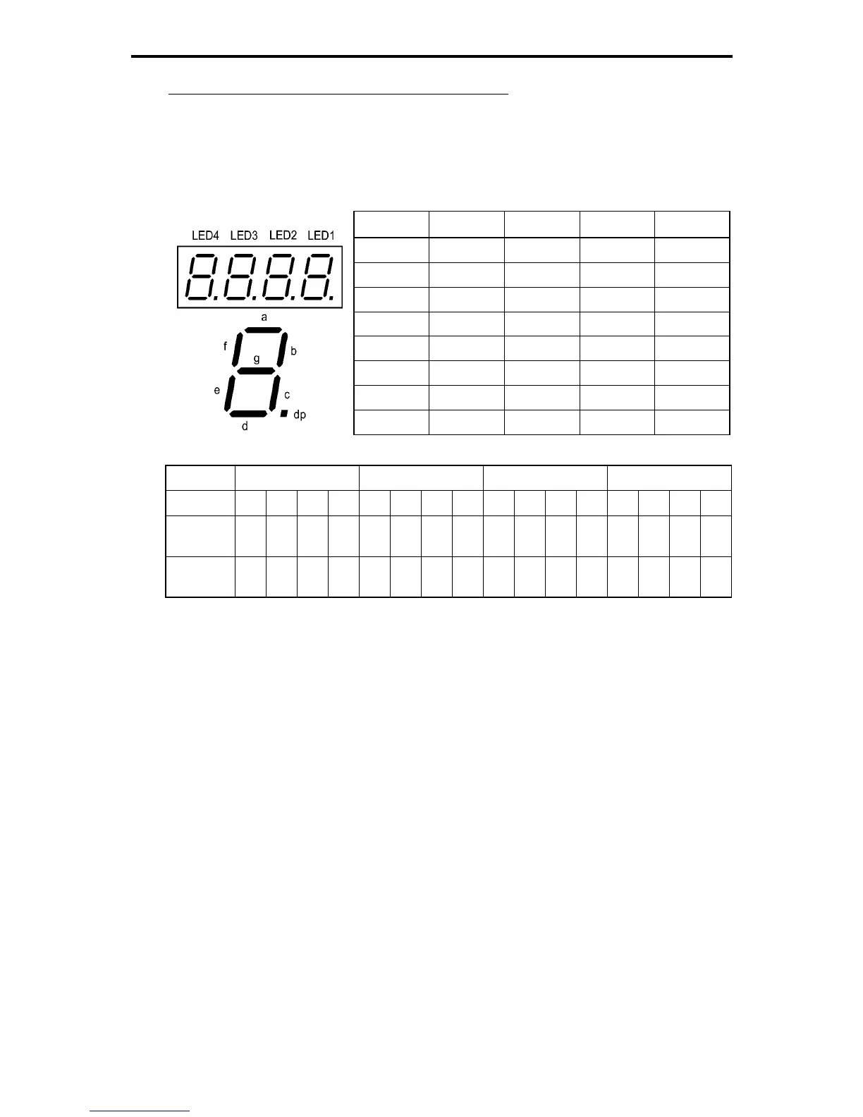
Displaying control circuit terminal on digital I/O interface cards
The LED monitor can also show the signal status of the terminals on the optional digital input and output
interface cards, just like the signal status of the control circuit terminals.
Digital I/O signals are assigned to the LED segments, as follows:
Table 3.4-12 Segment Display for External Signal Information (Digital Input and Output Interface Cards)
Segment
LED4 LED3 LED2 LED1
a ― O1 I9 I1
b ― O2 I10 I2
c ― O3 I11 I3
d ― O4 I12 I4
e ― O5 I13 I5
f ― O6 I14 I6
g ― O7 I15 I7
dp ― O8 I16 I8
LED No. LED4 LED3 LED2 LED1
Bit 15 14 13 12 11 10 9 8 7 6 5 4 3 2 1 0
Input
terminal
I16 I15 I14 I13 I12 I11 I10 I9 I8 I7 I6 I5 I4 I3 I2 I1
Output
terminal
- - - - - - - - O8 O7 O6 O5 O4 O3 O2 O1

 Loading...


