3.4 Programming Mode
3-33
Chapter 3
KEYPAD FUNCTIONS
z
Displaying I/O signal status in hexadecimal
Each I/O terminal is assigned to bit 15 through bit 0 in 16-digit binary. An unassigned bit is interpreted as
"0." Allocated bit data is displayed on the LED monitor as four hexadecimal digits (
0
to
f
each).
On the FRENIC-MEGA, digital input terminals [FWD] and [REV] are assigned to bits 0 and 1, respectively.
Terminals [X1] through [X9] are assigned to bits 2 through 10. The bit is set to "1" when the corresponding
input terminal is short-circuited (ON), and it is set to "0" when the terminal is open (OFF). For example,
when [FWD] and [X1] are ON (short-circuited) and all the others are OFF (open),
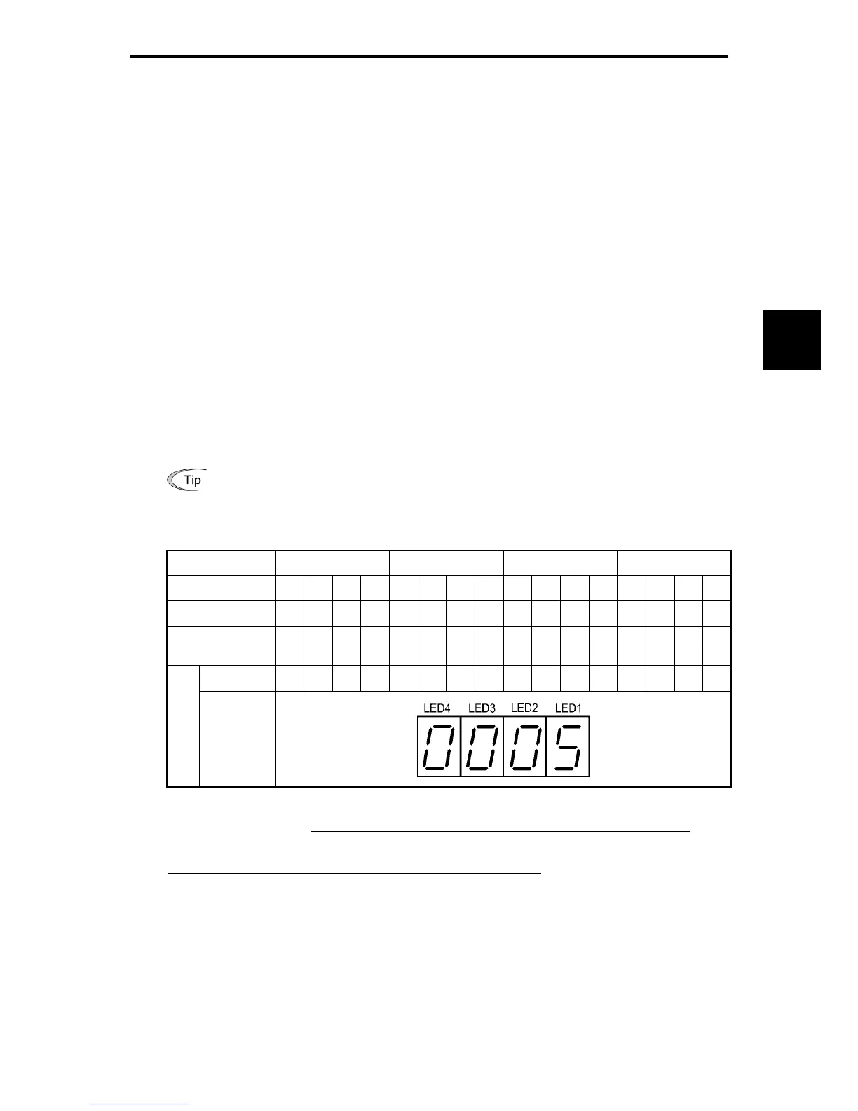
0005
is displayed on
LED4 to LED1.
Digital output terminals [Y1] through [Y4] are assigned to bits 0 through 3. Each bit is set to "1" when the
output terminal [Y1], [Y2], [Y3] or [Y4] is short-circuited with [CMY] (ON), and "0" when it is open (OFF).
The status of the relay contact output terminal [Y5A/C] is assigned to bit 4. It is set to "1" when the circuit
between output terminals [Y5A] and [Y5C] is closed. The status of the relay contact output terminals
[30A/B/C] is assigned to bit 8. It is set to "1" when the circuit between output terminals [30A] and [30C] is
closed, and "0" when the circuit between [30A] and [30C] is open. For example, if [Y1] is ON, [Y2] through
[Y4] are OFF, the circuit between [Y5A] and [Y5C] is open, and the circuit between [30A] and [30C] is
closed, then "
0101
" is displayed on the LED4 through LED1.
The table below presents bit assignment and an example of corresponding hexadecimal display on the
7-segment LED assigned to bits 15 through 0.
The segment display below indicates the ON/OFF status of the terminals, not the active/inactive
status of input/output.
Table 3.4-11 7-Segment LED for I/O Signal Status in Hexadecimal Display (Example)
LED No. LED4 LED3 LED2 LED1
Bit 15 14 13 121110987654 3 2 10
Input terminal
(RST) (XR)* (XF)*
- - X9 X8 X7 X6 X5 X4 X3 X2 X1 REV
Output terminal - - - - - - -
30A/
B/C
- - -
Y5A/C
Y4 Y3 Y2 Y1
Binary 0 0 0 000000000 0 1 01
Display example
(Input terminal)
Hexadecimal
LED
Monitor
–: No corresponding control circuit terminal exists.
* (XF), (XR), and (RST) are assigned for communications control.
Refer to "Displaying control I/O signal terminals under communications control" below.
Displaying control I/O signal terminals under communications control
Under communications control, input commands (function code S06) sent via RS-485 or other optional
communications can be displayed in two ways: "with ON/OFF of each LED segment" and "in
hexadecimal." The content to be displayed is basically the same as that for the control I/O signal terminal
status display; however, (XF), (XR), and (RST) are added as inputs. Note that under communications
control, the I/O display is in normal logic (using the original signals not inverted).
For details about input commands sent through the communications link, refer to the RS-485
Communication User's Manual and the instruction manual of communication-related options as well.

 Loading...


