5.4 Details of Function Codes
5-112
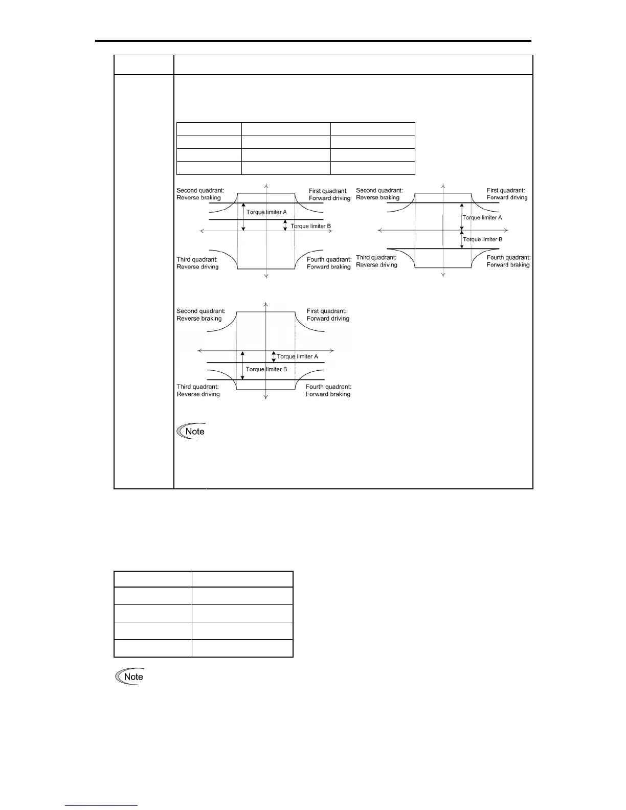
Data for H75 Target quadrants
Torque limiter A applies to the upper limit, and torque limiter B to the lower limit.
Depending upon the polarity of torque limiters A and B, the following patterns are available.
Table 5.4-49
Torque limiter A Torque limiter B
Pattern 1 Positive Positive
Pattern 2 Positive Negative
Pattern 3 Negative Negative
Pattern 1
Pattern 2
Pattern 3
2: Upper/lower
limits
y If the value of torque limiter A is less than that of torque limiter B, torque limiter A applies to
both the upper and lower limits.
y Selecting the "Upper/lower torque limits" may cause reciprocating oscillation between the
upper and lower limit values, depending upon a small difference between the upper and
lower limits, a slow response from the speed control sequence, and other conditions.
Torque limiters (F40, F41, E16 and E17) Data setting range: -300 to 300 (%), 999 (Disable)
These function codes specify the operation level at which the torque limiters become activated, as the
percentage of the motor rated torque.
Table 5.4-50
Function Code Name
F40
Torque limiter 1-1
F41
Torque limiter 1-2
E16
Torque limiter 2-1
E17
Torque limiter 2-2
Although the data setting range for F40, F41, E16, and E17 is from positive to negative values
(-300% to +300%), specify positive values in practice except when the "Upper/lower torque limits"
(H75 = 2) is selected. Specifying a negative value causes the inverter to interpret it as an absolute
value.
The torque limiter determined depending on the overload current actually limits the torque current
output. Therefore, the torque current output is automatically limited at a value lower than 300%,
the maximum setting value.

 Loading...


