5.4 Details of Function Codes
5-115
Details of
Function Codes
F40 to F42
E codes
C codes
P codes
H codes
A codes
b codes
r codes
J codes
d codes
U codes
y codes
Chapter 5 Function Code
To improve the accuracy of slip compensation, perform auto-tuning.
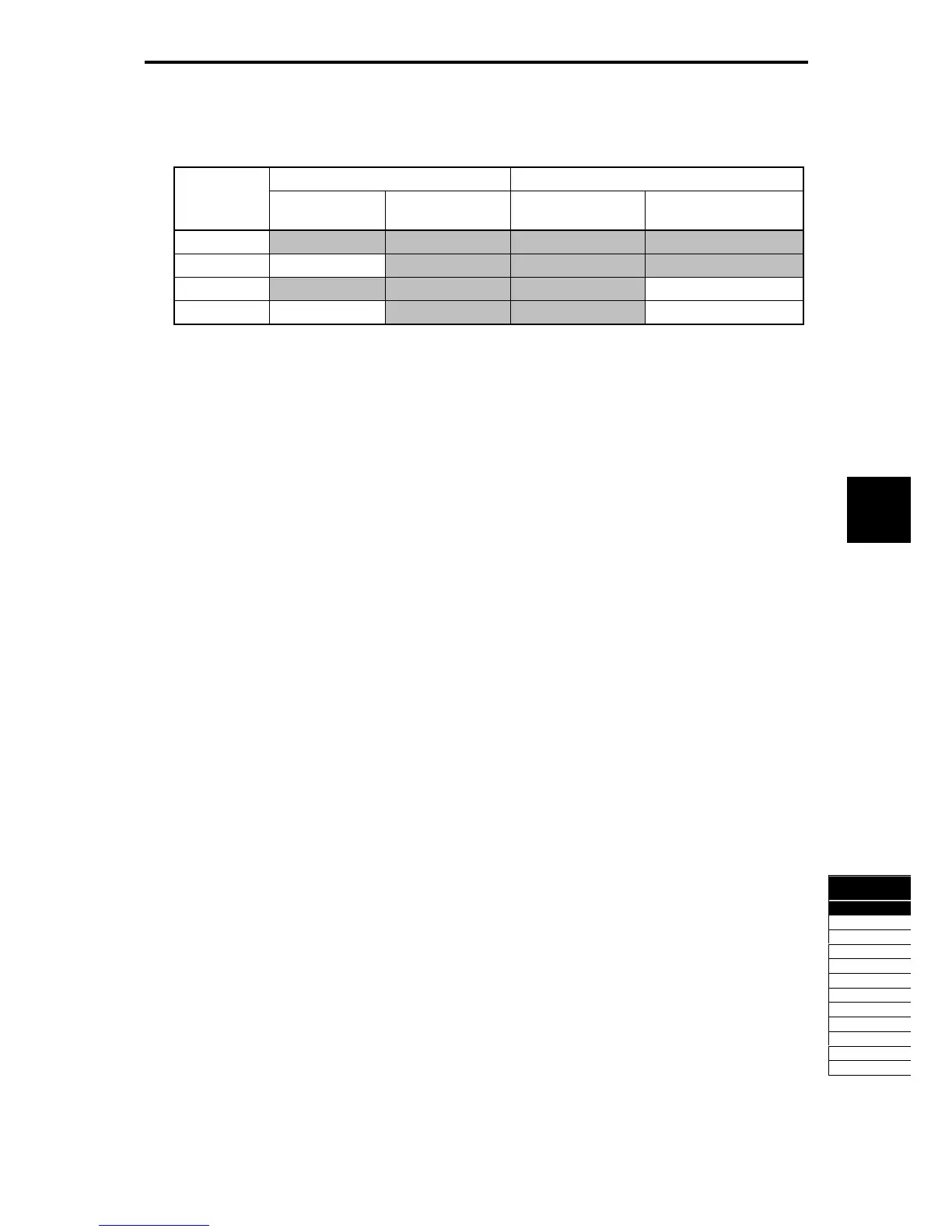
H68 enables or disables the slip compensation function according to the motor driving conditions.
Table 5.4-55
Motor driving conditions Motor driving frequency zone
Data for H68
Accl/Decel During constant
speed
Base frequency
or below
Above the base
frequency
0 Enable Enable Enable Enable
1 Disable Enable Enable Enable
2 Enable Enable Enable Disable
3 Disable Enable Enable Disable
Dynamic torque vector control
To get the maximal torque out of a motor, this control calculates the motor torque matched to the load
applied and uses it to optimize the voltage and current vector output.
Selecting the dynamic torque vector control automatically enables the auto-torque boost and slip
compensation. This control is effective for improving the system response to external disturbances such as
load fluctuations, and the motor speed control accuracy.
Note that the inverter may not respond to a rapid load fluctuation since this control is an open-loop V/f control
that does not perform current control, unlike vector control. Other advantage of this control is that the
maximum torque per output current is larger than that of vector control.
V/f control with speed sensor
Applying any load to an induction motor causes a rotational slip due to the motor characteristics, decreasing
the motor rotation. Under V/f control with speed sensor, the inverter detects the motor rotation using the
encoder mounted on the motor shaft and compensates for the decrease in slip frequency by the PI control to
match the motor rotation with the reference speed. This improves the motor speed control accuracy.
Dynamic torque vector control with speed sensor
The difference from "V/f control with speed sensor" stated above is to calculate the motor torque matched to
the load applied and use it to optimize the voltage and current vector output for getting the maximal torque
out of a motor. This control is effective for improving the system response to external disturbances such as
load fluctuations, and the motor speed control accuracy.
Vector control without speed sensor
This control estimates the motor speed based on the inverter's output voltage and current to use the
estimated speed for speed control. It also decomposes the motor drive current into the exciting and torque
current components, and controls each of those components in vector. No PG (pulse generator) interface
card is required. It is possible to obtain the desired response by adjusting the control constants (PI
constants) using the speed regulator (PI controller).
The control regulating the motor current requires some voltage margin between the voltage that the inverter
can output and the induced voltage of the motor. Usually a general-purpose motor is so designed that the
voltage matches the commercial power. Under the control, therefore, it is necessary to suppress the motor
terminal voltage to the lower level in order to secure the voltage margin required. However, driving the motor
with the motor terminal voltage suppressed to the lower level cannot generate the rated torque even if the
rated current originally specified for the motor is applied. To ensure the rated torque, it is necessary to
increase the rated current. (This also applies to vector control with speed sensor.)
The control is not available in MD-mode inverters, so do not set F42 data to "5" for those inverters.

 Loading...


