5.4 Details of Function Codes
5-119
Chapter 5 Function Code
Details of
Function Codes
F43 to F52
E codes
C codes
P codes
H codes
A codes
b codes
r codes
J codes
d codes
U codes
y codes
F50 to
F52
Electronic Thermal Overload Protection for Braking Resistor
(Discharging capability, Allowable average loss and Resistance)
These function codes specify the electronic thermal overload protection feature for the braking resistor.
Set the discharging capability, allowable average loss and resistance to F50, F51 and F52, respectively.
These values are determined by the inverter and braking resistor models. For the discharging capability,
allowable average loss and resistance, refer to [3] "Specifications" in Chapter 11, Section 11.4.1 "Braking
resistor (DBR) and braking unit."
The values listed in the tables are for standard models and 10% ED models of the braking resistors which
Fuji Electric provides. When using a braking resistor of any other manufacturer, confirm the corresponding
values with the manufacture and set the function codes accordingly.
Depending on the thermal marginal characteristics of the braking resistor, the electronic thermal
overload protection feature may act so that the inverter issues the overheat protection alarm
d
even if the actual temperature rise is not large enough. If it happens, review the relationship
between the performance index of the braking resistor and settings of related function codes.
Using the standard models of braking resistor or using the braking unit and braking resisto
together can output temperature detection signal for overheat. Assign terminal command TH
("Enable external alarm trip") to any of digital input terminals [X1] to [X9], [FWD] or [REV], and
connect that terminal and its common terminal to braking resistor's terminals 2 and 1.
Calculating the discharging capability and allowable average loss of the braking resistor and configuring the
function code data
When using any non-Fuji braking resistor, inquire of the resistor manufacturer about the resistor rating and
then configure the related function codes.
The calculation procedures for the discharging capability and allowable average loss of the braking resistor
differ depending on the application of the braking load as shown below.
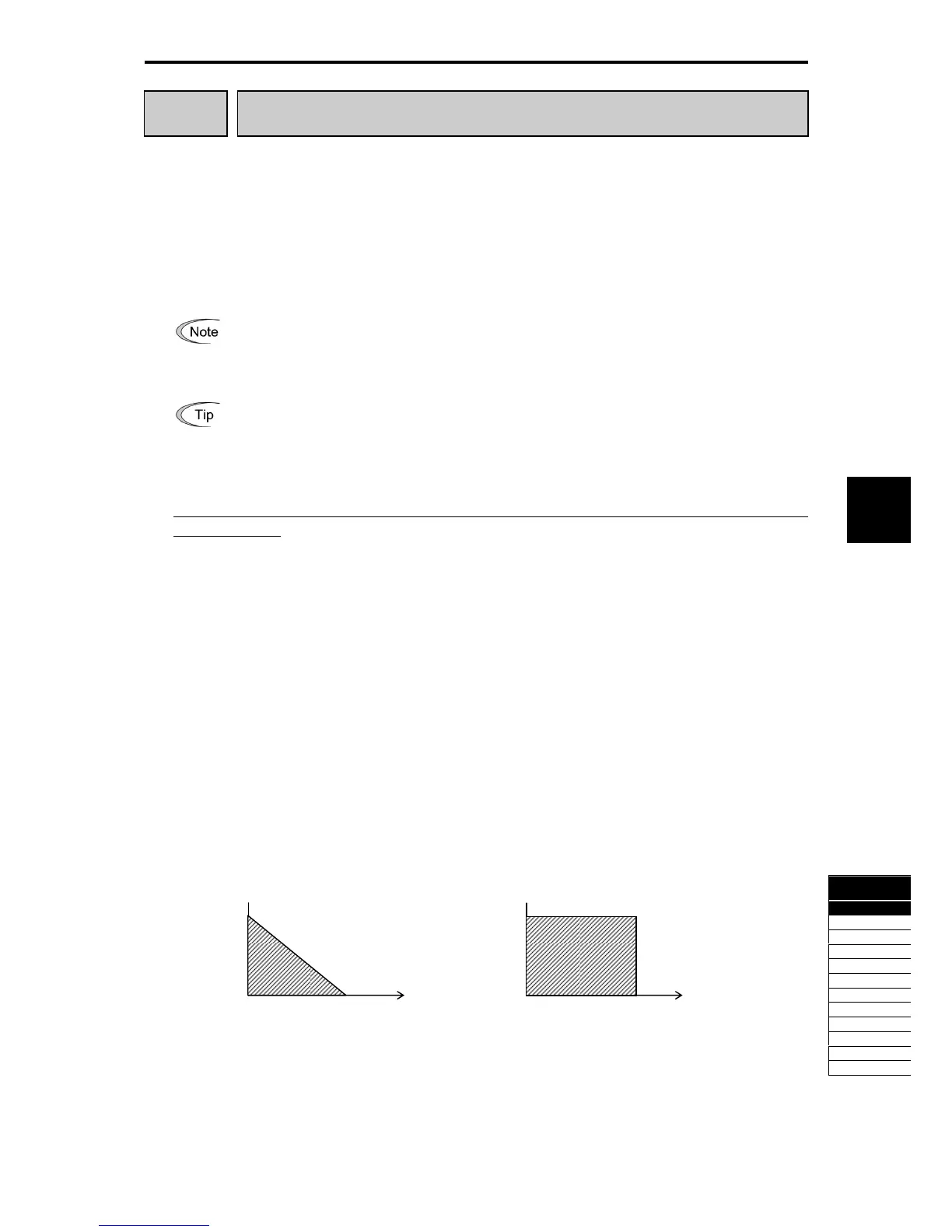
<Applying braking load during deceleration>
In usual deceleration, the braking load decreases as the speed slows down. In the deceleration with constant
torque, the braking load decreases in proportion to the speed.
Use Expressions (1) and (3) given below to calculate the discharging capability and the allowable average
loss.
<Applying braking load during running at a constant speed>
Different from during deceleration, in applications where the braking load is externally applied during running
at a constant speed, the braking load is constant.
Use Expressions (2) and (4) given below to calculate the discharging capability and the allowable average
loss.
Figure 5.4-43 Figure 5.4-44
Applying braking load during deceleration Applying braking load during running at a constant speed
Time
Braking load (kW)
Time
Braking load (kW)

 Loading...


