5.4 Details of Function Codes
5-144
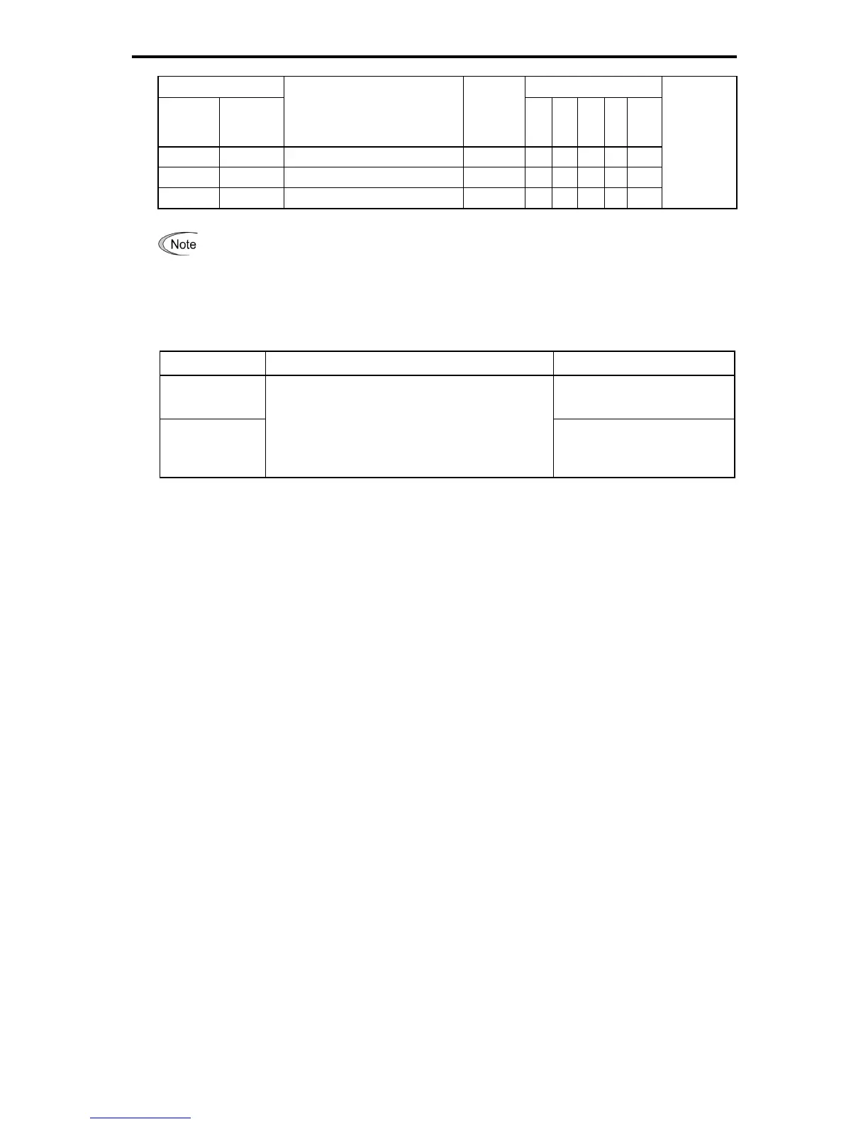
Data Control Method
Active
ON
Active
OFF
Defined Functions Signal Name
V/f
PG
V/f
PG
Less
PG
Torque
Control
Related
Function
Code/
Related Signal
(Data)
113 1113
Customizable logic output signal 3
CLO3
{ { { { {
114 1114
Customizable logic output signal 4
CLO4
{ { { { {
115 1115
Customizable logic output signal 5
CLO5
{ { { { {
Functions that has "-" in the data active OFF field, the negative logic setting is not possible.
Assignment of running RUN and inverter outputting RUN2 (Function code data = 0, 35)
This function is used as a signal that tells whether the inverter is running or not. If assigned in Active OFF,
these signals can be used as the in-stop signal.
Output Signal Basic Function Remarks
RUN
Turns off during DC braking or
dew condensation prevention
RUN2
These signals turn on when the inverter is running.
Under V/f control, these signals come on if the output
frequency exceeds the starting frequency, and go off if
it drops below the stop frequency. The RUN signal can
also be used as a "Speed valid" signal.
Turns on during DC braking,
pre-exciting, zero speed control,
or dew condensation prevention
Under vector control, both RUN and RUN2 come on also when zero speed control or servo-lock function is
enabled.
Frequency (speed) arrival signal FAR and Frequency (speed) arrival signal 3 FAR3 (Function code data =
1, 72)
The ON signal is output when the difference between the output frequency (detected speed) and set
frequency (speed command) comes within the frequency arrival detected width (function cede E30). (
Function code E30)
Assignment of Frequency (speed) detected FDT, Frequency (speed) detected 2 FDT2, and Frequency
(speed) detected 3 FDT3
(Function code data = 2, 31, 58)
The ON signal is output when the output frequency (speed detected value) becomes higher than the
detected level set to the operation level of the frequency detection, and it goes OFF when the output
frequency becomes below the [frequency detected value (operation level) - hysteresis width]. (
Function
code E31, E32)
Assignment of Undervoltage stopping LU (Function code data = 3)
This output signal comes on when the DC link bus voltage of the inverter drops to equal or below the
undervoltage level, the ON signal is output. When this signal is on, the inverter cannot run even if a run
command is given. When the voltage recovers and exceeds the undervoltage detected level, the signal turns
off. This signal is ON also when the undervoltage protective function is activated so that the motor is in an
abnormal stop state (e.g., tripped).
Assignment of torque polarity detected B/D (Function code data = 4)
The inverter outputs the driving or braking torque judgment signal by the torque calculated value or torque
instruction value calculated in the inverter inside. In case of the driving torque, the off signal is output. In case of
the braking torque, the on signal is output.
Assignment of inverter output limiting IOL and inverter output limiting (with delay) IOL2
(Function code data = 5, 22)

 Loading...


