5.4 Details of Function Codes
5-147
Details of
Function Codes
F codes
E20 to E27
C codes
P codes
H codes
A codes
b codes
r codes
J codes
d codes
U codes
y codes
Chapter 5 Function Code
Assignment of pattern operation stages No.1, 2, 4 STG1, STG2, and STG4 (Function code data = 18, 19,
20)
During the pattern operation, the currently-operating stage is output.
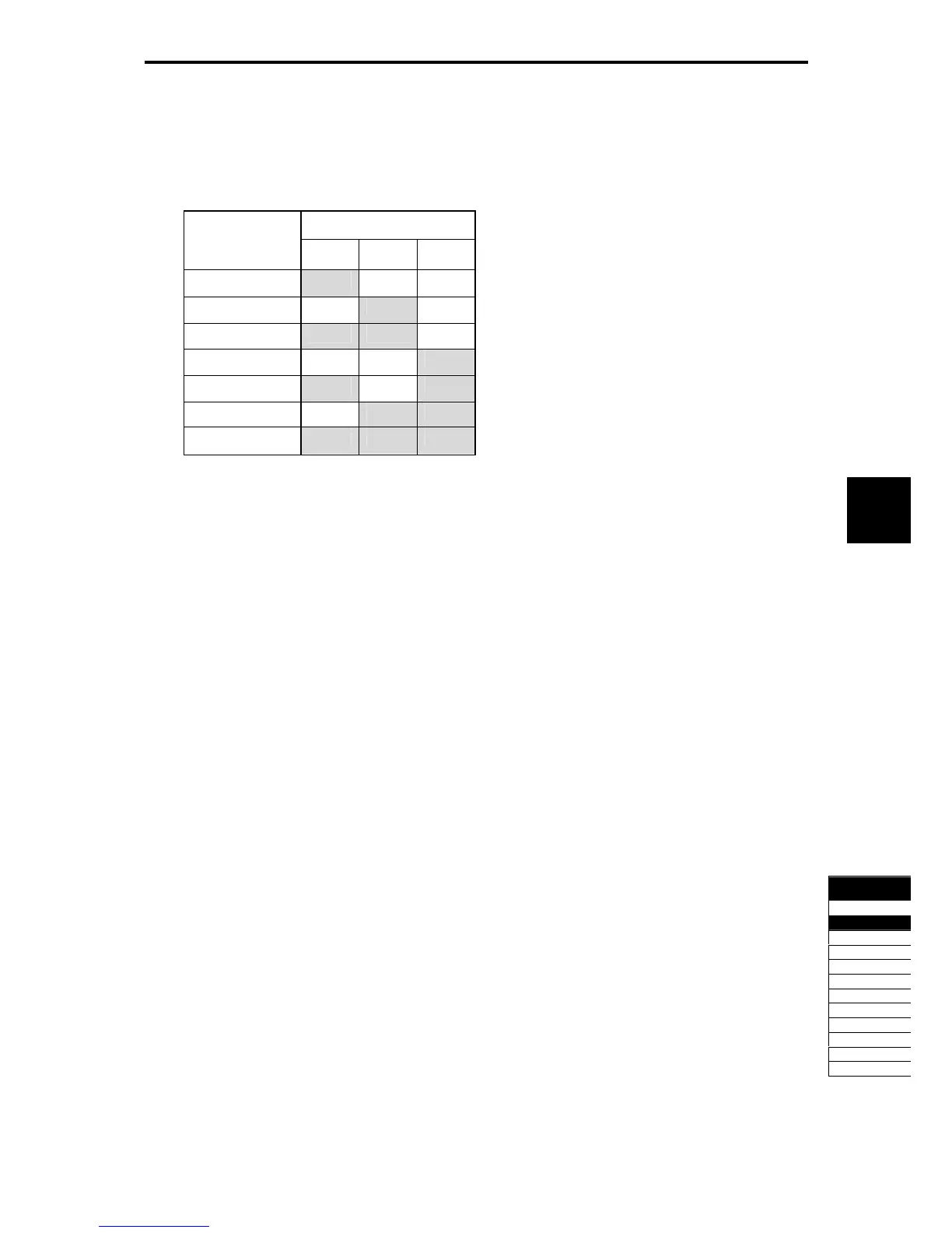
Table 5.4-76
Output Terminal Signal
Operation
Pattern
Stage No.
STG1 STG2 STG4
Stage 1 ON OFF OFF
Stage 2 OFF ON OFF
Stage 3 ON ON OFF
Stage 4 OFF OFF ON
Stage 5 ON OFF ON
Stage 6 OFF ON ON
Stage 7 ON ON ON
Assignment of Cooling fan ON-OFF control FAN (Function code data = 25)
While the cooling fan ON-OFF control is valid (H06 = 1), this output signal is on while the cooling fan is in
operation, and off while the cooling fan is stopped. This signal can be used to make the cooling system of
peripheral equipment interlocked for an ON/OFF control.
(
Function code H06)
Assignment of retry operating TRY (Function code data = 26)
This function outputs ON signal during the retry operation (alarm auto resetting).
(
Function code H04, H05)
Assignment of universal DO U-DO (Function code data = 27)
This function enables to connect the output terminal of the inverter assigned to the universal DO to the digital
signal input of the inverter periphery device and give commands to the periphery equipment via RS-485 or
fieldbus. The universal DO can be used as a simple digital output independent of the inverter operation.
For the access to the universal DO via the RS-485 or fieldbus, see the respective instruction manuals.
Assignment of Cooling fin overheat early warning OH (Function code data = 28)
This function detects the early warning before the overheat trip (
0h1
) is output, and used as an appropriate
procedure.
The signal turns on when [(overheat trip (
0h1
) temperature) - 5°C] or higher
The signal turns off when [(overheat trip (
0h1
) temperature) - 8°C] or lower
This signal turns on when the locked status of the internal air circulation DC fan (45 kW or above for 200 V
class series, 75 kW or above for 400 V class series) has detected.
Assignment of synchronous completion signal SY (Function code data = 29)
When the control target comes into the synchronous completion detect angle during the synchronous
operation, the signal outputs the ON signal.
For details, see the PG Interface Card Instruction Manual.

 Loading...


