5.4 Details of Function Codes
5-162
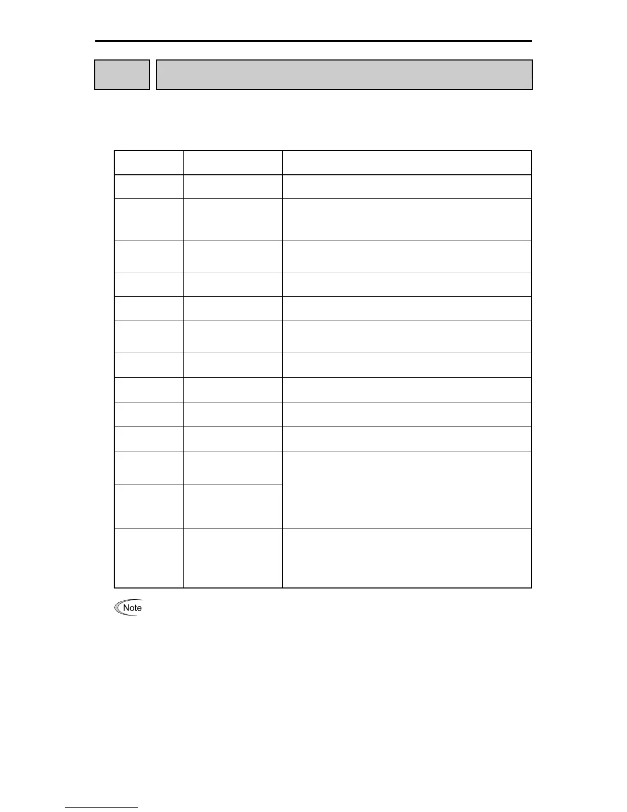
E61 to
E63
Terminal [12], [C1], [V2] (Extended Function Select)
This function selects functions of terminals [12], [C1], and [V2], respectively.
(When it is used for the frequency setting, setting is not required.)
Table 5.4-88
E61, E62, E63
Data
Function Description
0
No Assignment of
extension function
-
1
Auxiliary frequency
command 1
Auxiliary frequency input to be added to the frequency command 1
(F01). Will not be added to any settings other than frequency
command 1 (frequency command 2 and multi-frequency commands,
etc.).
2
Auxiliary frequency
command 2
Auxiliary frequency input added to all frequency settings. Auxiliary
frequency is added to Frequency command 1, 2, and multi-frequency
commands.
3 PID command 1
Inputs command sources such as temperature and pressure under
PID control. You also need to set function code J02.
5 PID feedback value
Inputs feedback amounts such as temperature and pressure under
PID control.
6 Ratio setting
It is used for line speed constant control by the diameter calculation
of winder and ratio operation of multiple inverters. Therefore, it is
integrated to the latest frequency command as a ratio.
7
Analog torque
limit value A
Used when analog inputs are used as torque limiters. (
Function
code F40)
8
Analog torque
Limit value B
Used when analog inputs are used as torque limiters. (
Function
code F40)
10 Torque command
Analog inputs to be used as torque commands under torque control.
(
Function code H18)
11 Torque current command
During the torque control, analog input is used as the torque current
command. (
Function code H18)
17
Forward (FWD) side
speed
limit value
18
Reverse (REV) side
speed
limit value
Under torque control, the motor speed limit value can be set with [12],
[C1], and [V2] terminals. To limit the motor speed to the maximum
frequency (F02, A01, b01, and r01), set the analog input (max. input)
to the maximum value.
When using this function, it is recommended to use d35 (overspeed
detect level) together.
Note: The function codes C31 to C45 (analog input adjustment) are
applied to these analog inputs.
20 Analog input monitor
By inputting analog signals from various sensors such as the
temperature sensors in air conditioners to the inverter, you can
monitor the state of external devices via the communications link. By
using an appropriate display coefficient, you can also display various
values converted to physical quantities such as temperature and
pressure.
If these terminals have been set up to have the same data, the operation priority is given in the
following order: E61 > E62 > E63
When UP/DOWN control (F01, C30 = 7) is selected as the frequency setting, the auxiliar

 Loading...


