5.4 Details of Function Codes
5-189
Details of
Function Codes
F codes
E codes
C codes
P codes
H18 to H27
A codes
b codes
r codes
J codes
d codes
U codes
y codes
Chapter 5 Function Code
H26 and
H27
Thermistor (for Motor) (Operation Selection and Level)
These function codes specify the PTC (Positive Temperature Coefficient)/NTC (Negative Temperature
Coefficient) thermistor embedded in the motor. Set H26 and H27 for enabling the thermistor to protect the
motor from overheating or output an alarm signal.
Thermistor (for motor) (Operation selection) (H26)
H26 selects the function operation mode (protection or alarm).
Table 5.4-122
Data for H26 Operation
0
Disable
1
When the voltage sensed by PTC thermistor exceeds the detection level, motor protective
function (alarm
0h4
) is triggered, causing the inverter to enter an alarm stop state.
2
When the voltage sensed by the PTC thermistor exceeds the detection level, a motor
alarm signal is output but the inverter continues running.
It is necessary to assign the thermistor detect (PTC) THM (Function code E20 to E24, E27
data = 56).
3
It is set when the NTC thermistor, which is integrated in the motor (VG motor) exclusively
used for the Fuji vector control, is used. The motor temperature is detected, and it is used
for control. If the motor overheats and the temperature exceeds the protection level, the
inverter issues the Motor protection alarm
0h4
and stops the motor.
If H26 data is set to "1" or "2" (PTC thermistor), the inverter monitors the voltage sensed by PTC thermistor
and protect the motor even when any of the 2nd to 4th motors is selected. If NTC thermistor is selected (H26
= 3) and any of the 2nd to 4th motors is selected, the inverter does not perform these functions.
Thermistor (operation level) (H27)
H27 sets the operation level of the PTC thermistor.
- Data setting range: 0.00 to 5.00 (V)
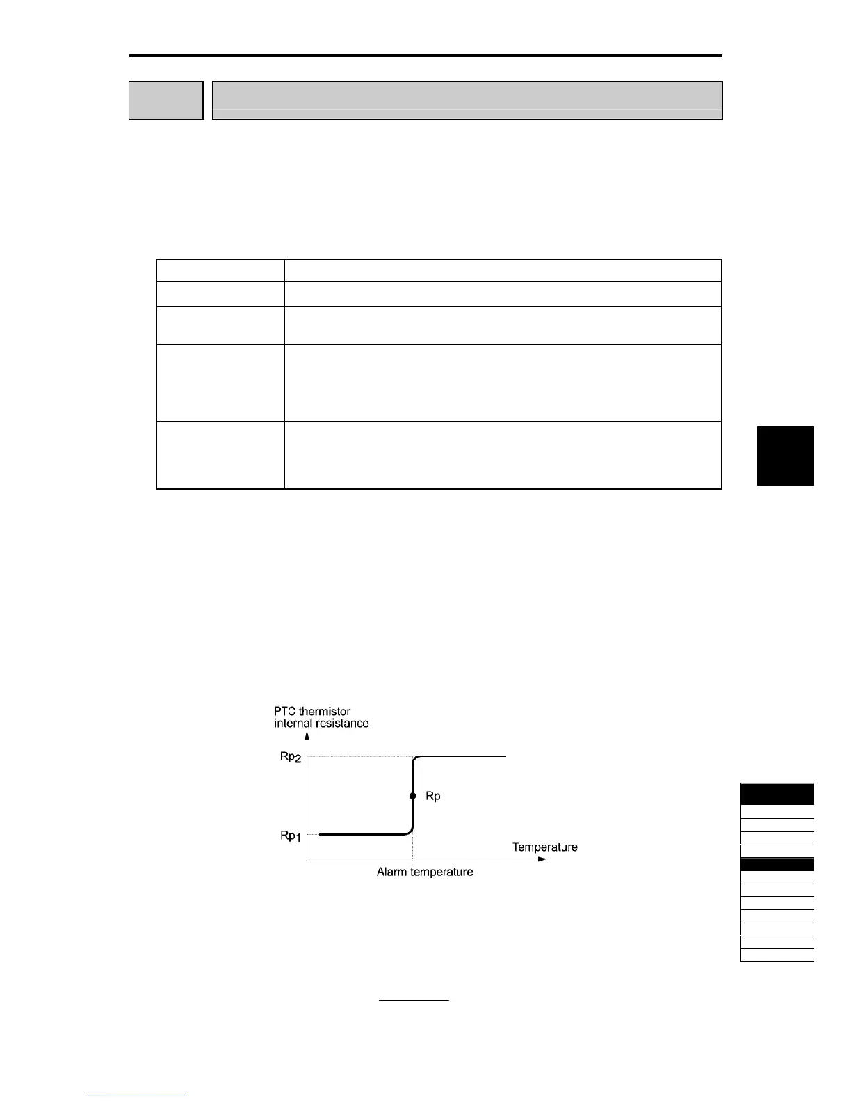
The protection temperature is determined according to the characteristics of the PTC thermistor. The internal
resistance of the PTC thermistor will significantly change at the protection temperature. The detection level
(voltage) is specified based on the change of the internal resistance.
Fig. 5.4-84
Suppose that the resistance of the PTC thermistor at the alarm temperature is Rp, the detection level V
v2
is
calculated by the expression below. Set the calculation result to H27.
(V)10.5
Rp27000
Rp
×V2V
+
=

 Loading...


