5.4 Details of Function Codes
5-218
Selecting Feedback Terminals
For feedback control, determine the connection terminal according to the type of the sensor output.
- If the sensor is a current output type: Use the current input terminal [C1] of the inverter.
- If the sensor is a voltage output type: Use the voltage input terminal [12] of the inverter or the terminal
[V2].
For details, see E61, E62, and E63.
<Application example: Process control> Major application: Air conditioners, fans and pumps
The operating range for PID process control is internally controlled as 0% through 100%. For the given
feedback input, determine the operating range to be controlled by means of gain setting.
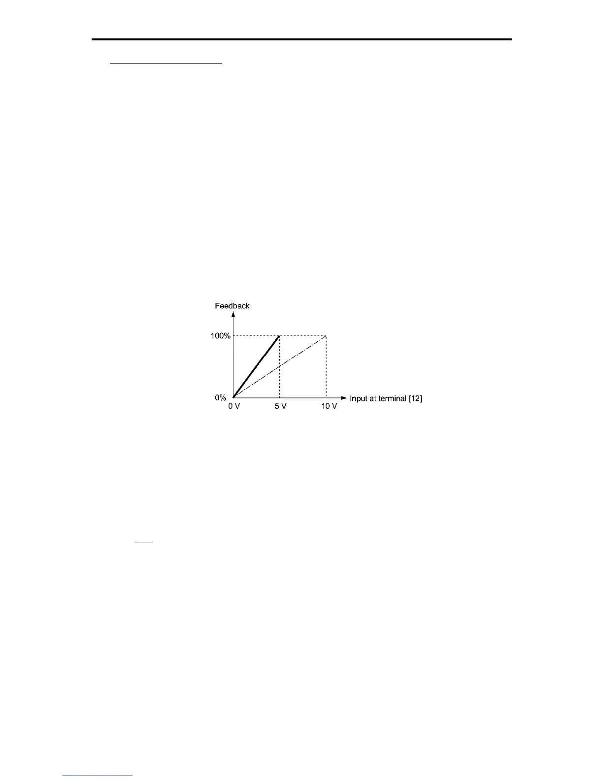
(Example) When the output level of the external sensor is within the range of 1 to 5 V:
- Use terminal [12] designed for voltage input.
- Set the gain (C32) at 200% in order to make the maximum value (5 V) of the external sensor's output
corresponds to 100%. The input specification of terminal [12] is 0 to 10 V for 0 to 100%. Therefore, due to
the ratio of 10 V/5 V, the specification becomes 200% setting. (The bias setting of the feedback is
invalid.)
Fig. 5.4-96
<Application examples: Dancer control> Major application: Winding system
(Example 1) When the output level of the external sensor is ±7 V
- Use terminal [12] designed for voltage input to both polarities.
- When the external sensor's output is of bipolar, the inverter controls the speed within the range of 100%.
The external sensor ±7 V is set to ±100%; therefore, the gain setting (C32) is set to
143%
V7
V10
≈
.

 Loading...


