5.4 Details of Function Codes
5-242
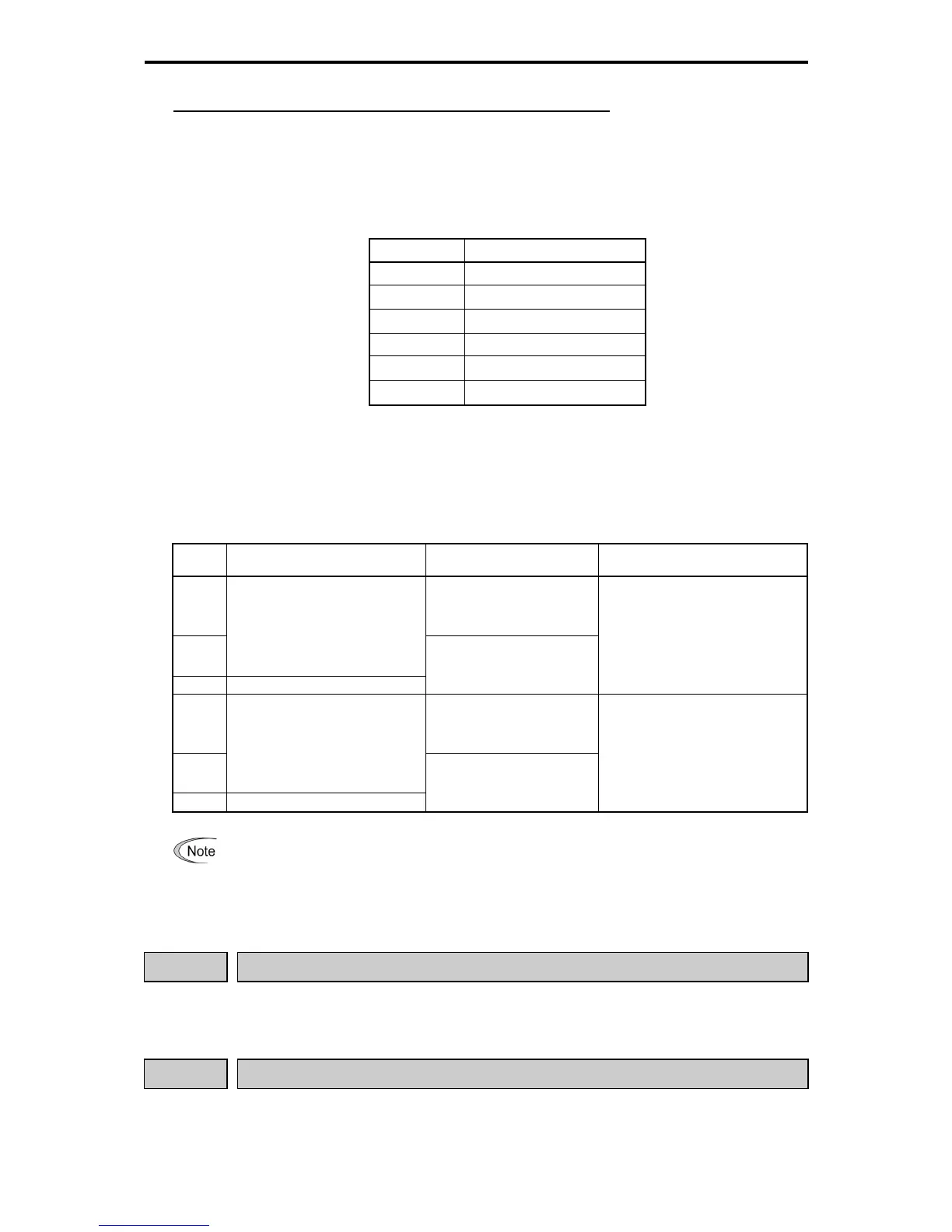
PG Error Detected PG-ERR (Function Code E20 to E24, E27 Data = 76)
Speed Agreement/PG Error (Detection Range (d21) and Detection Timer (d22)), PG Error Selection (d23)
- Data setting range: d21 = 0.0 to 50.0 (%) ··· Max. Speed/100%
d22 = 0.00 to 10.00 (s)
d23 = 0 to 5
Table 5.4-165
Data for d23 Function
0 Continue to run 1
1
Alarm (
ereE
) Stop 1
2
Alarm (
ereE
) Stop 2
3 Continue to run 2
4
Alarm (
ereE
) Stop 3
5
Alarm (
ereE
) Stop 4
If the deviation of the speed controller (deviation between the speed command and estimated speed/detected
speed) is out of the set range (d21) for the set period (d22), the inverter judges it as a PG error.
Data setting for d23, however, defines the detection conditions, the error processing after the error detection, and
the range of error detection.
Table 5.4-166
d23
Data
Detection Condition Processing After Detection
Speed Command > Error Detect Width
at F04
0 In this case, the PG error
detect PG-ERR signal is
output, and the inverter
continues operating.
1
When the inverter cannot follow the
speed command (after soft-starting)
due to a heavy overload or the like
so that the detected speed is slow
against the reference speed, the
inverter does not interpret this
situation as a PG error.
2 There is no excluding condition.
ere
alarm is
inverter coast to a stop
Constant at "Detect width = d21 x
max. frequency" even at equal to or
higher than the base frequency (F04).
3 In this case, the PG error
detect PG-ERR signal is
output, and the inverter
continues operating.
4
When the inverter cannot follow the
speed command (after soft-starting)
due to a heavy overload or the like
so that the detected speed is slow
against the reference speed, the
inverter does not interpret this
situation as a PG error.
5 There is no excluding condition.
ere
alarm is
inverter coast to a stop
Constant at Detect width = "d21 x
max. frequency" when equal to or
lower than the base frequency (F04).
"Detect width = d21 x speed
command x max. frequency / base
frequency" when equal to or higher
than the base frequency (F04).
When limiting functions such as the torque limit and droop control are enabled, an actual speed
becomes greatly different from the speed command, and the deviation becomes large. In this case,
the situation may be judged PG error, and the inverter may get tripped. To avoid this incident,
select the operation continuation (d23 = 0) to prevent the inverter from tripping.
d24
Zero Speed Control (See F23)
For the zero speed control, see the description of the function code F23.
d25
ASR Switching Time (See A42)
For the ASR switching time, see the description of the function code A42.

 Loading...


